Hydraulic intensifiers

a technology of hydraulic intensifier and intensifier, which is applied in the direction of positive displacement liquid engine, mechanical apparatus, pumps, etc., can solve the problems of high cost, complicated devices of hydraulic intensifiers, and high cost of current hydraulic intensifiers, and achieve the effect of a larger cross-sectional area

Inactive Publication Date: 2009-12-24
VETCO GRAY CONTROLS
View PDF2 Cites 68 Cited by
  • Summary
  • Abstract
  • Description
  • Claims
  • Application Information

AI Technical Summary

Benefits of technology

[0008]Disclosed herein is a hydraulic intensifier having a piston and cylinder assembly with a first piston in a chamber of a low pressure cylinder and a second piston in a chamber of a high pressure cylinder, the first and second pistons being coupled together and the first piston having a larger cross-sectional area than the second piston, a high pressure output coupled

Problems solved by technology

The supply of high pressure fluid via the umbilical is not favoured by well operators, as a high pressure feed within the umbilical, needing a much greater wall thickness than usual, results in much greater umbilical and handling costs.
The alternate operation of the piston sets is controlled by a complicated arrangement of valves and springs and since these and the piston sets are integrated into one assembly, current hydraulic intensifiers are complicated devices, which

Method used


Image

  • Hydraulic intensifiers
  • Hydraulic intensifiers

Examples


Embodiment Construction

[0018]The method and system of the present disclosure will now be described more fully hereinafter with reference to the accompanying drawings in which embodiments are shown. The method and system of the present disclosure may be in many different forms and should not be construed as limited to the illustrated embodiments set forth herein; rather, these embodiments are provided so that this disclosure will be through and complete, and will fully convey its scope to those skilled in the art. Like numbers refer to like elements throughout.

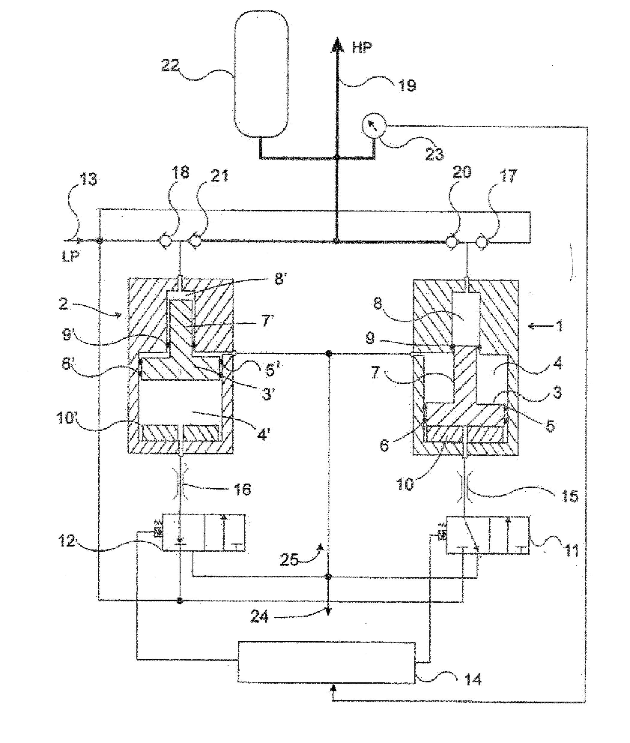
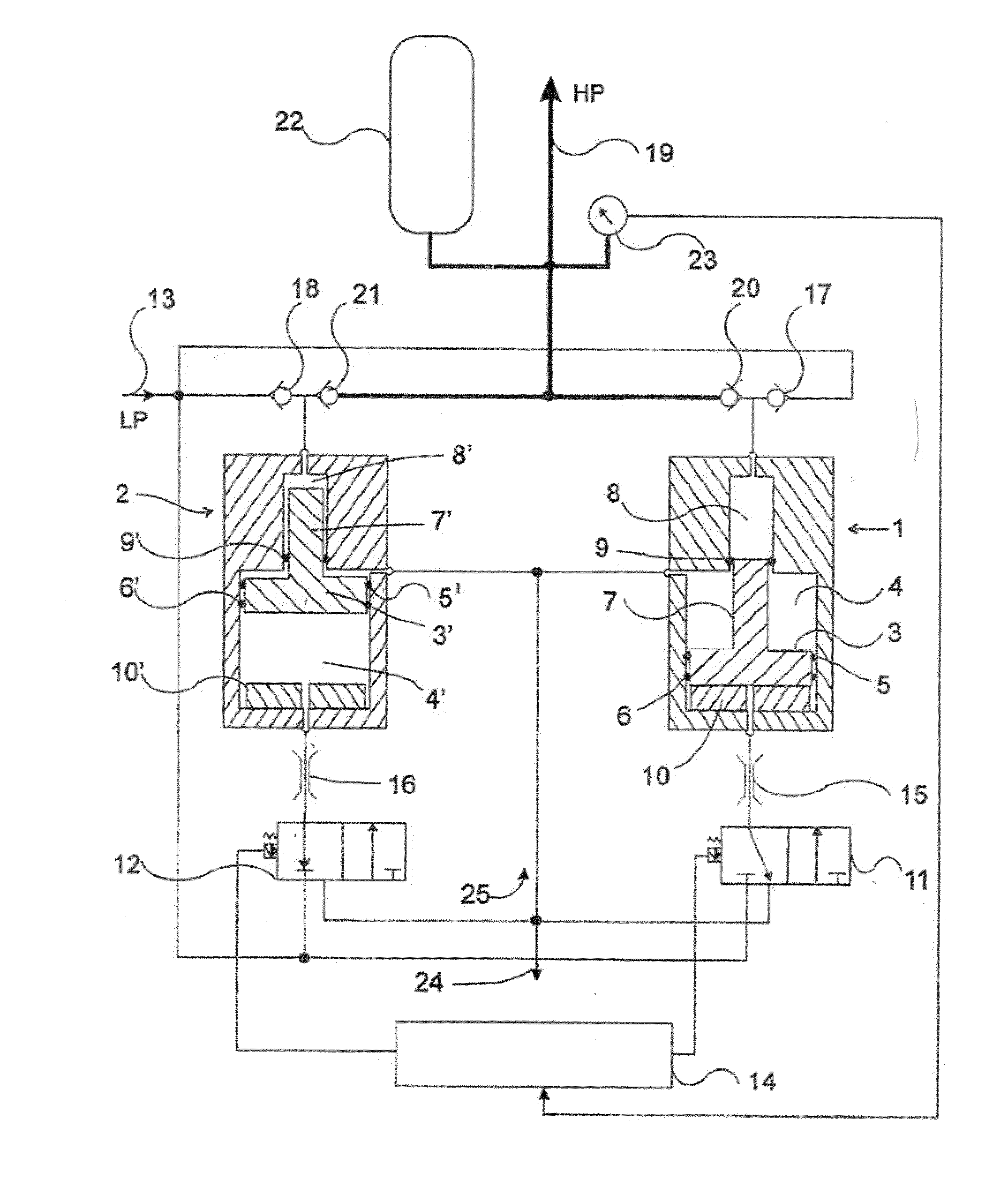
[0019]An example of a hydraulic intensifier for a subsea hydrocarbon extraction or injection well is provided in FIG. 1. Two piston and cylinder assemblies 1 and 2, which may be identical, are shown in sectioned view. An associated hydraulic circuit is shown schematically. Each piston assembly has a large cross-sectional area piston 3, 3′ depending from one side and a smaller cross-sectional area piston 7, 7′ depending from its opposite end. The larg...


PUM


Abstract

A hydraulic intensifier with a piston and cylinder assembly (1) having a first piston (3) in a chamber (4) of low pressure cylinder and a second piston (7) in a chamber (8) of a high pressure cylinder. The first and second pistons are coupled together and the first piston has a larger cross-sectional area than the second piston. A high pressure output (19) is coupled to the chamber of the high pressure cylinder, there being; means (13) for supplying low pressure hydraulic fluid to the chamber of the low pressure cylinder; an electrically operated directional control valve (11) for controlling the supply of low pressure hydraulic fluid to the chamber of the low pressure cylinder; and electronic means (14) for controlling operation of the directional control valve.

Description

CROSS REFERENCE TO RELATED APPLICATIONS[0001]This Application relates claims priority to and the benefit of co-pending United Kingdom Patent Application No. 0811205.4 filed on 19 Jun. 2008, the full disclosure of which is hereby incorporated fay reference.BACKGROUND[0002]1. Field of Invention[0003]The present invention relates to hydraulic intensifiers.[0004]2. Description of Related Art[0005]Hydraulic intensifiers are devices that generate high hydraulic pressure from a low pressure source. When employed in subsea wells such as hydrocarbon production or injection wells, they provide a source of high pressure hydraulic fluid for the operation of hydraulically actuated devices, such as valves and flow control chokes. Such wells are, typically, supplied with low pressure hydraulic fluid via an umbilical, which can be in excess of 100 Km in length. The supply of high pressure fluid via the umbilical is not favoured by well operators, as a high pressure feed within the umbilical, needin...

Claims


Application Information

Patent Timeline
IPC IPC(8): F04B49/06F04B7/00
CPCF15B3/00E21B33/0355F04B9/105F04B9/109
Inventor GILL, SIMON DAVIDROBERTS, TIMOTHY JAMES
Owner VETCO GRAY CONTROLS
Why Eureka
Try Eureka