Portable Medical Foam Apparatus

Inactive Publication Date: 2009-12-24
LEVY FRANK
View PDF3 Cites 20 Cited by
  • Summary
  • Abstract
  • Description
  • Claims
  • Application Information

AI Technical Summary

Benefits of technology

[0016]The foam generation tip includes a novel arrangement by which compressed air enters the first end of the foam generation tip, the interior of the foam generation tip as an inlet for providing medical solution to the tip, and the pressure produced within the foam generation tip draws its solution from the inlet into the interior of the tip. The compressed air continues to travel towards the second end of the foam generation tip onto which a membrane is affixed. The membrane provides a surface at which the medical solution mixes with the compressed air and the medical solution foams. The compressed air passes through the membrane and lifts the foams off the membrane outward from the foam generation tip. Thus, the solution, now foamed by the compressed gas, can be delivered.
[0028]In medical uses, CO2 is used because it is safer and has less complications than air or oxygen in the same uses. CO2 diffuses more naturally in body tissues and is absorbed in the body more rapidly and with less side effects.
[0030]It is used for imaging by infiltrating the tissues, body cavities, and abdomen for better visualization. The CO2 can also expand internal body cavities and tissues enabling better diagnostic techniques.
[0032]CO2 is used to aerate and subsequently cause foam for schlerotherapy solution. CO2, once introduced to a vein, obliterates the lumen of the vein to eliminate the varicose and spider vein problem.
[0040]Previous methods utilizing large CO2 tanks and regulators are dangerous because of the risk of a seal, valve, or part malfunction causing a projectile in a medical setting. The present invention is safer as it eliminates this possibility of malfunction.
[0044]The invention can be used by filling of the syringe directly, as opposed to the current system which requires the use of a filling bag which can not always eliminate the oxygen that is delivered into the syringe.

Problems solved by technology

The limiting case of the Venturi effect is choked flow, in which a constriction in a pipe or channel limits the total flow rate through the channel because the pressure cannot drop below zero in the constriction.

Method used


Image

  • Portable Medical Foam Apparatus
  • Portable Medical Foam Apparatus
  • Portable Medical Foam Apparatus

Examples


Embodiment Construction

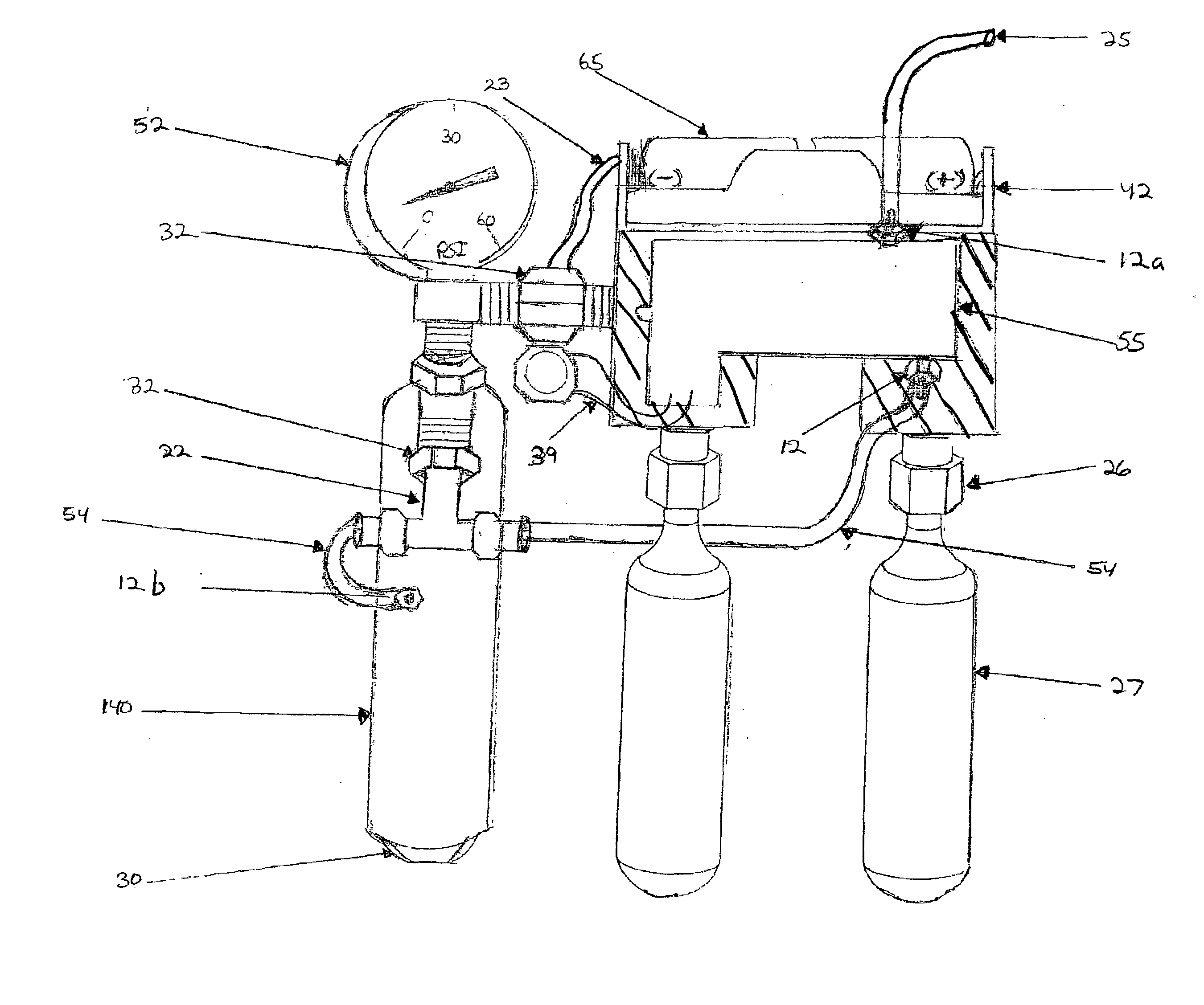
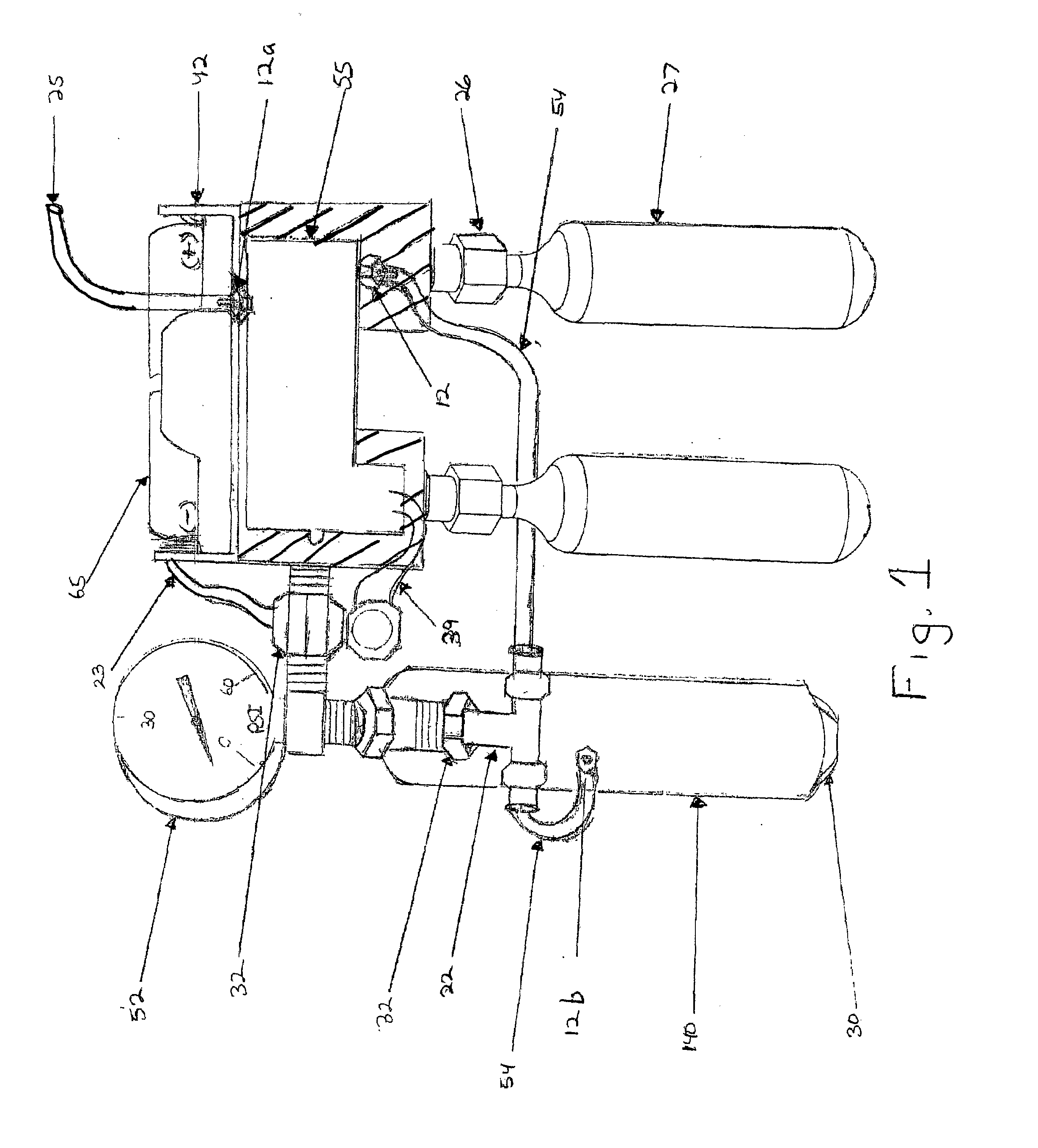
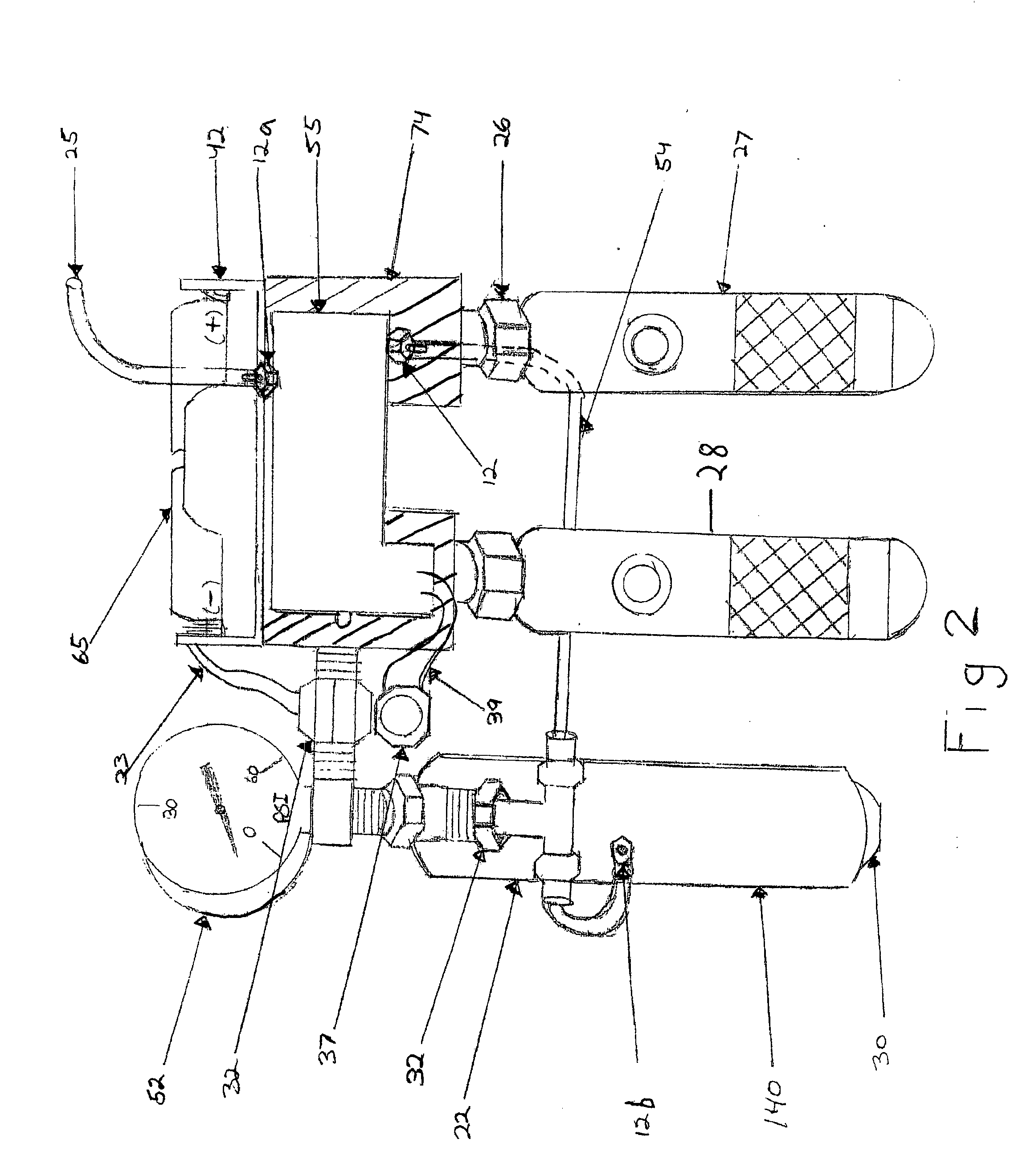
[0051]In FIG. 1 compressed gas unit 1 comprises solenoid 55 with at least one compressed gas cylinder. In one embodiment, compressed gas cylinder 27 is 25 g or larger. Compressed gas cylinder 27 is secured into position to unit 1 by means of cylinder cartridge puncture valve 26 and T “puncture” fitting 74.

[0052]In a preferred embodiment, cylinder cartridge puncture valve 26 has a mechanism for piercing cylinder 27, as is known, and holding or securing said cylinder in place.

[0053]Compressed air enters solenoid 55 from compressed gas cylinder 27 by means of cylinder cartridge puncture valve 26 and T “puncture” fitting 74. Compressed gas unit 1 has at least one battery 65, held in place by battery holder 42, for providing electrical power by which solenoid 55 may be activated and then regulated by pressure activation switch or actuator 37. Battery 65 supplies power to solenoid 55 through battery to switch wire assembly 23, which is secured in place by pressure nut 32. Compressed air u...


PUM


Abstract

An apparatus for producing medical foam having a foam generation unit including a fluid reservoir, a fluid delivery line and a foam generation tip; and a compressed gas unit including at least one container of compressed gas, a source of electric power, and a gas regulator valve.

Description

INDEX TO RELATED APPLICATIONS[0001]This application is a continuation-in-part of U.S. patent application Ser. No. 11 / 945,674 filed Nov. 27, 2007 which claims the benefit of U.S. Provisional Patent Application Ser. No. 60 / 867,323 filed Nov. 27, 2006 the disclosures of which are incorporated herein by reference in their entirety.BACKGROUND OF THE INVENTION[0002]The present invention utilizes Venturi effect to produce the foams and protect them from the apparatus. The present invention is simple to manufacture and use because it does not require an impeller and incorporated fan with a foam generator in order to create foam / foams and dispense them from the apparatus.[0003]The Venturi effect is an example of Bernoulli's principle, in the case of incompressible fluid flow through a tube or pipe with a constriction in it. The fluid velocity must increase through the constriction to satisfy the equation of continuity, while its pressure must decrease due to conservation of energy: the gain ...

Claims


Application Information

Patent Timeline
Patent Type & Authority Applications(United States)
IPC IPC(8): A61M5/155B67D5/54B67D7/72
CPCA61B17/12022A61B17/12109A61B17/12186F25D3/10F25C3/00F25C2303/044A61B2017/00778
Inventor LEVY, FRANK
Owner LEVY FRANK
Why Eureka
Try Eureka