Assisted sighting system for snipers

a technology for snipers and snipers, applied in the field of sniper sighting systems, can solve the problems of multiple shots, long range hits, and shooting at ranges that are difficult to hit, so as to improve the grip and control of the shooter, and improve the accuracy

Inactive Publication Date: 2009-12-31
LOCKHEED MARTIN CORP
View PDF8 Cites 69 Cited by
  • Summary
  • Abstract
  • Description
  • Claims
  • Application Information

AI Technical Summary

Benefits of technology

[0011]Yet another aspect of the present invention is to provide a method of improving a shooter's accuracy when firing ammunition from a weapon, the method comprising illuminating a target with a ranging signal generated by a laser, collecting with a focal plane array backscatter radiation generated by the ranging signal interacting with optical communication 38 corrective aiming instructions 40, 42 (shown in FIG. 5) to the telescopic sight 24 that may be seen by the sharpshooter 28 in a viewing area 44 of the telescopic sight 24. The sharpshooter 28 may then adjust the aim at the distant target 34 appropriately. While the present drawings and discussion relate to an embodiment of the invention where the spotter controls the spotter scope, the invention could also be constructed so that the sharpshooter controls both the spotter scope and the rifle with the telescopic sight. Alternatively, the features of the scope 26 may be incorporated into the rifle 22.
[0012]Turning now to FIGS. 2-4, the spotter scope 26 is shown and, as will be described, includes the necessary hardware and software for computing distances to distant targets, profiling the wind between the spotter

Problems solved by technology

For instance, a 10 mile-per-hour crosswind could easily result in a shooter missing a target at a range as short as 400 meters.
Between the factors internal and external to a firearm, hitting a target at long range can be a challenge.
However, efficiency and stealth are highly prized by the shooting pair, so missed shots and multiple shots are undesirable.
Methods for measuring wind velocity have been developed, but are not optimal to the gun sight arts.
However, attempts to implement this practic

Method used


Image

  • Assisted sighting system for snipers
  • Assisted sighting system for snipers
  • Assisted sighting system for snipers

Examples


Embodiment Construction

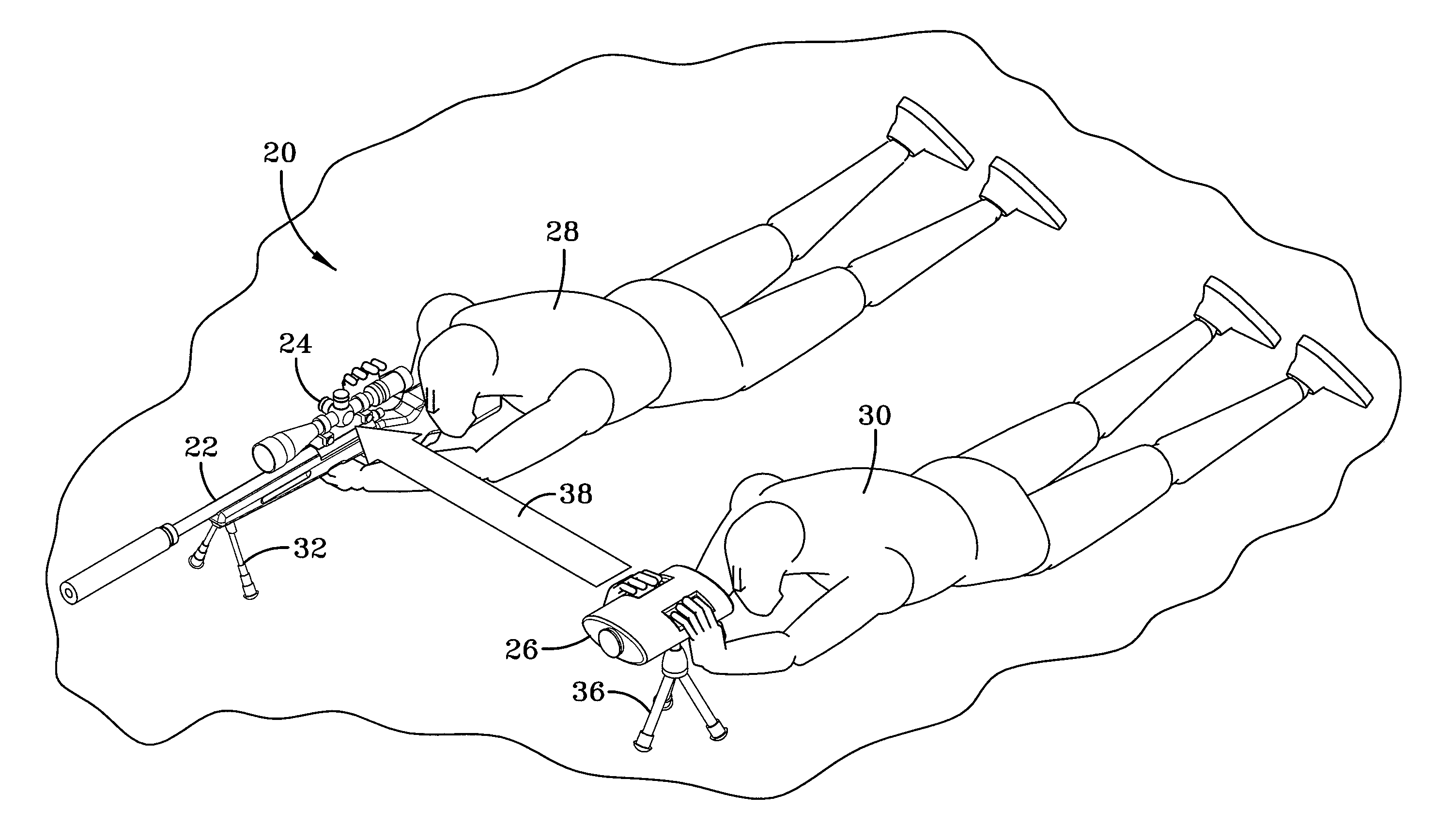
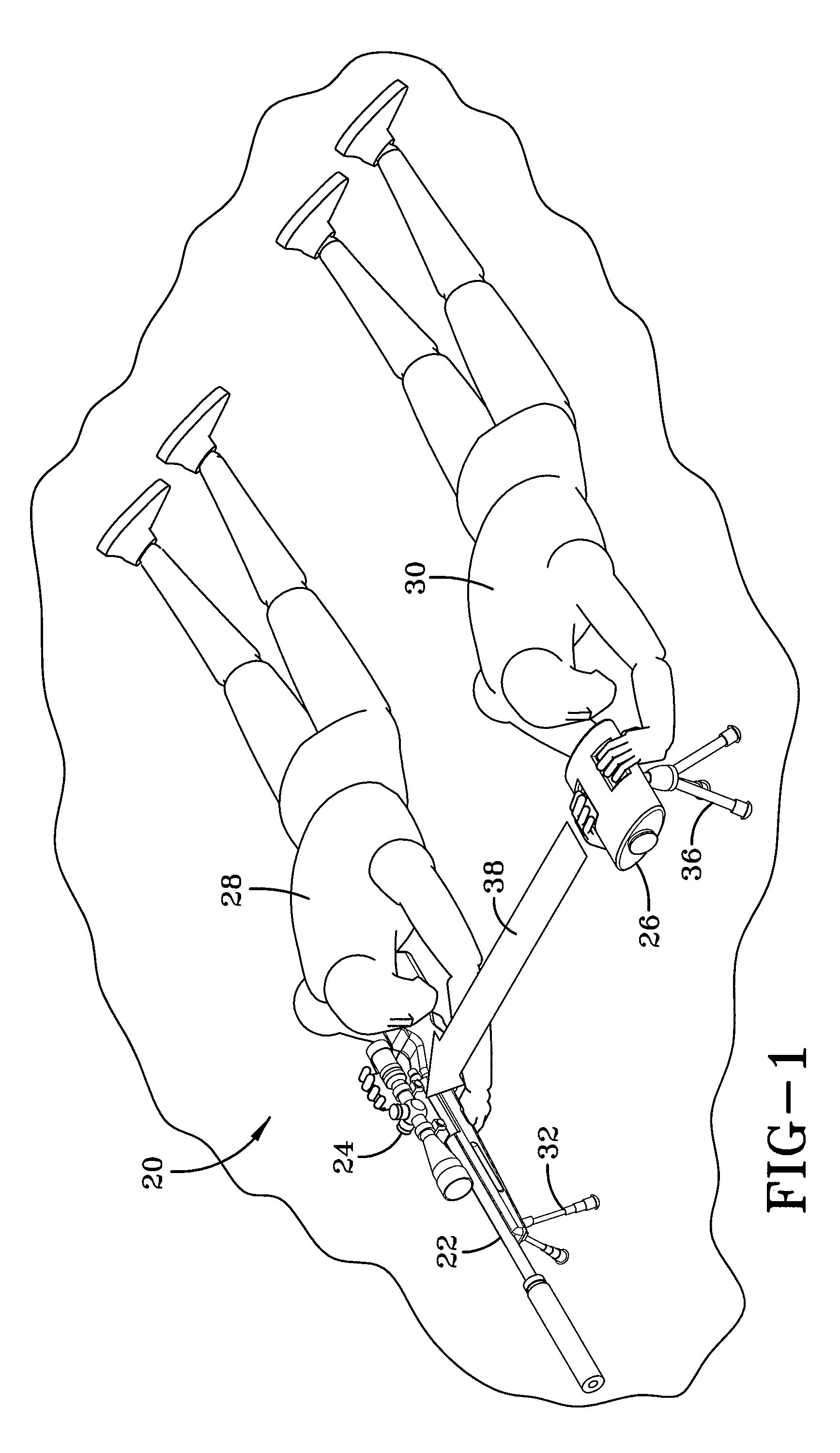
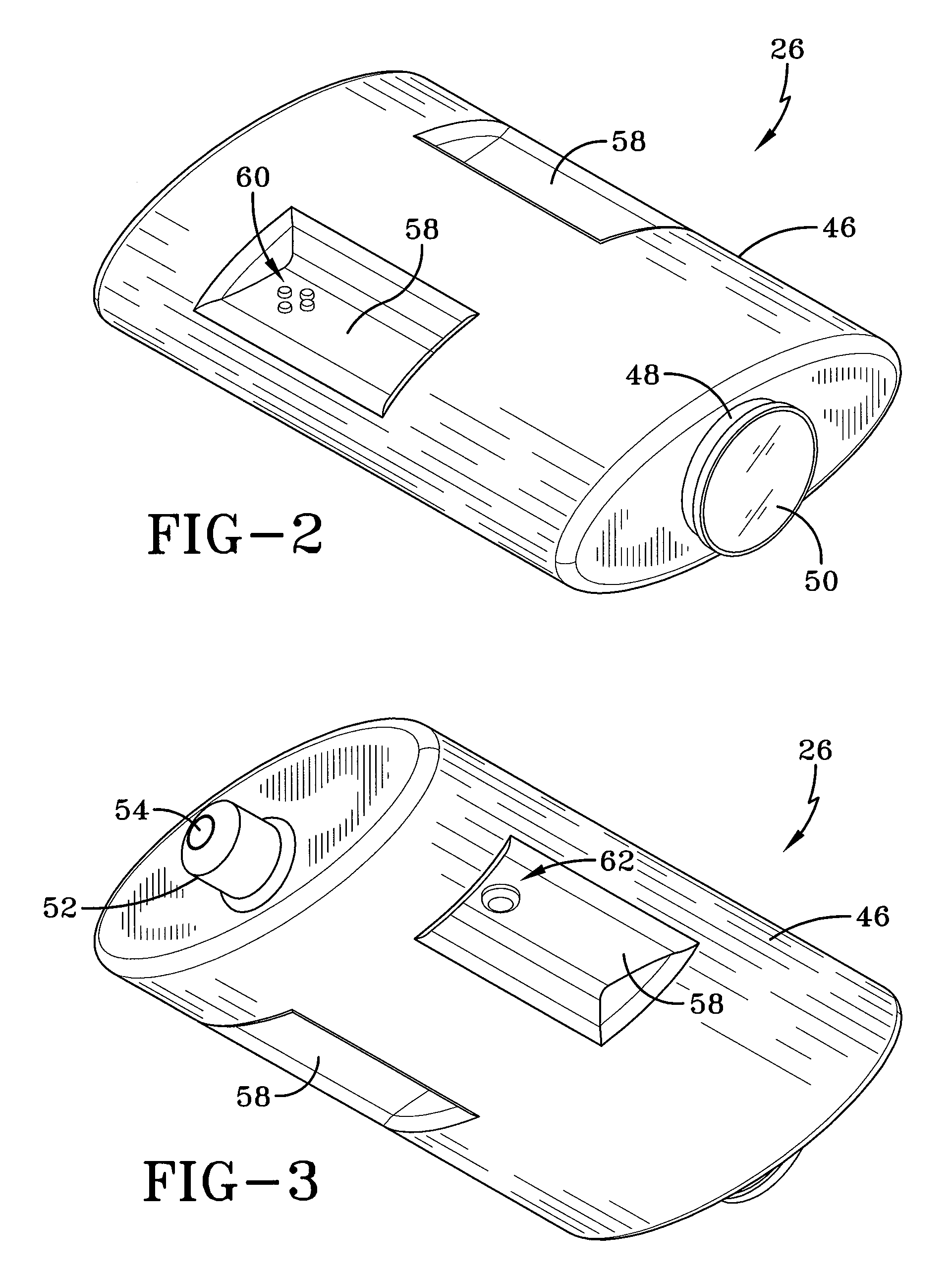
[0021]Referring now to the drawings, an assisted sighting system is designated generally by the numeral 20 and is configured for use in conjunction with a rifle 22 or other small-arms weapon and includes a telescopic sight 24 or similar sighting device along with a spotter scope 26. According to the embodiment shown in FIG. 1, a sharpshooter 28, also referred to herein as a sniper, and spotter 30 lie prone in simulated operational positions. The sharpshooter 28 controls the rifle 22, optionally supported by a bipod 32, and looks at a distant target 34 (shown in FIG. 4) through the telescopic sight 24. The spotter 30 looks at the same distant target 34 using the spotter scope 26, which may be supported by a tripod 36. As will be discussed further below, the spotter scope 26 computes the distance to the distant target and a wind profile for the wind between the spotter scope 26 and the distant target 34. The spotter scope 26 then communicates by wired or wireless of light and measurin...


PUM


Abstract

A spotter scope including an illuminator that generates a ranging signal is disclosed. The spotter scope further includes an imaging device with a focal plane array which detects backscatter radiation created by the ranging signal, and a controller which calculates a distance to a target. The controller also creates a wind profile between the spotter scope and the target based on scintillation statistics of backscatter detected by the focal plane array and provides corrective aiming instructions based on the wind profile.

Description

CROSS-REFERENCE TO RELATED APPLICATION[0001]This application claims priority of U.S. Provisional Application Ser. No. 61 / 133,047 filed Jun. 25, 2008, which is incorporated herein by reference.TECHNICAL FIELD[0002]Generally, the present invention relates to a sighting system for small-arms weapons. Specifically, the present invention relates to a sighting system for small-arms weapons that can calculate the distance to a target, deduce the effects of the spatial wind profile along the intended trajectory, and provide appropriate corrective aiming instructions to a shooter.BACKGROUND[0003]Sighting devices have long been used to help shooters improve the placement of their small-arms weapons' fired shots. Small-arms weapons include those firearms that an individual may carry and use. Many handguns, for instance, include unmagnified iron sight devices with horizontal and vertical reference points that allow a shooter to align the gun parallel to the shooter's line of sight. Other firear...

Claims


Application Information

Patent Timeline
IPC IPC(8): F41G1/38G01C3/08
CPCF41G1/38F41G1/473F41G3/02G01S17/95F41G3/08F41G3/14G01C3/08F41G3/06Y02A90/10
Inventor KELLY, KURTIS L.
Owner LOCKHEED MARTIN CORP
Why Eureka
Try Eureka