Cogeneration system

Active Publication Date: 2009-12-31
AISIN SEIKI KK
View PDF28 Cites 23 Cited by
  • Summary
  • Abstract
  • Description
  • Claims
  • Application Information

AI Technical Summary

Problems solved by technology

Thus, the hot water storage/supply circuit is inevitably provided at the cogeneration system.
In this case, the hot water storage tank has generally a sufficient capacity for accommodating a hot water supply load for home usage, such as 100 liters or more, which leads to a large tank and a large space and an increased cost for installing the tank.
Thus, when the hot water supply load is not present (i.e., the hot water supply is not required or used) for a long period of time, the surplus heat cannot be stored

Method used


Image

  • Cogeneration system
  • Cogeneration system
  • Cogeneration system

Examples


Embodiment Construction

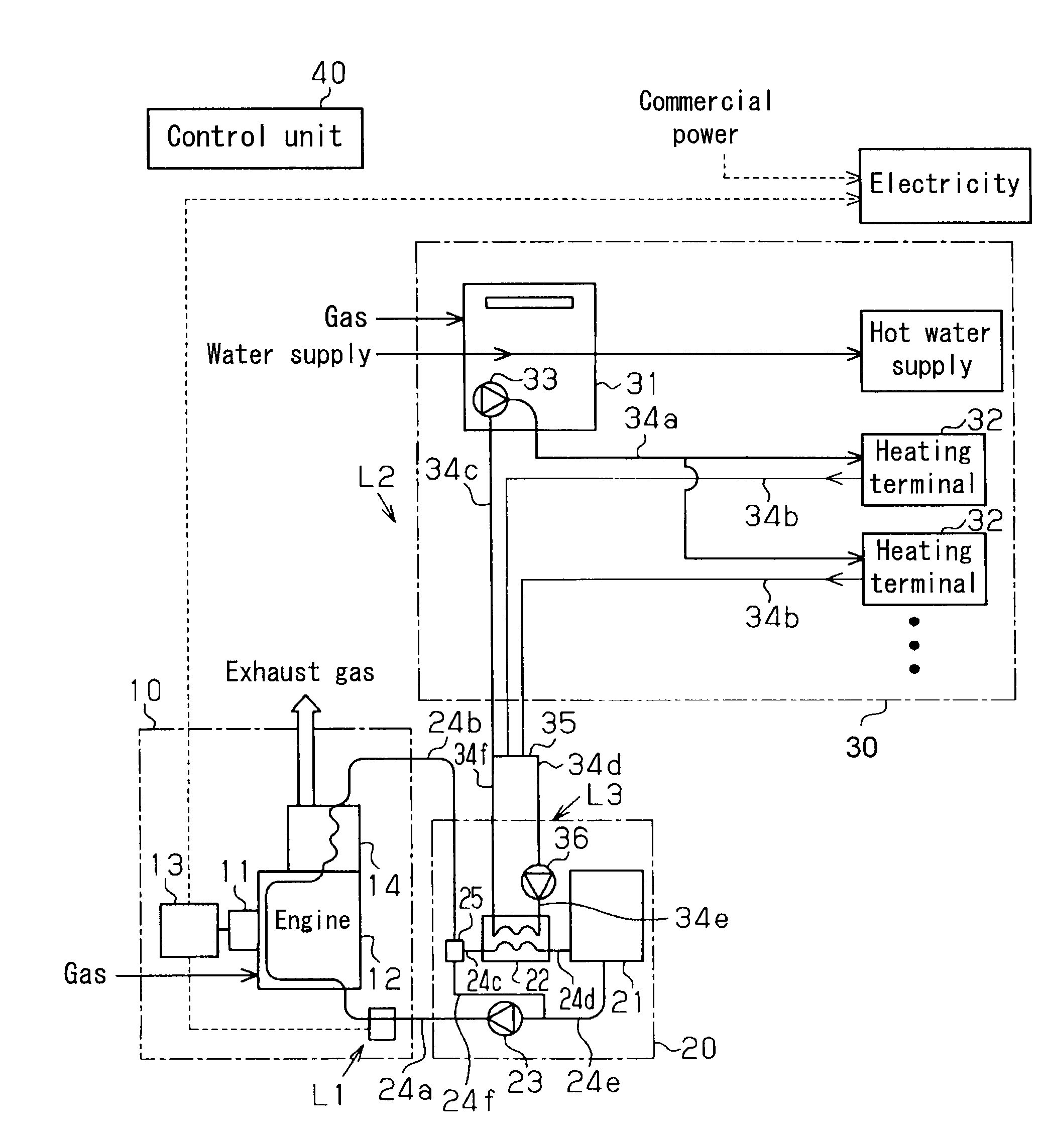
[0013]An embodiment of the present invention will be explained with reference to the attached drawings. As illustrated in FIG. 1, a cogeneration system of the present embodiment includes a power generation unit 10, a buffer tank unit 20, a hot water heater 30, and a control unit 40 for controlling the power generation unit 10, the buffer tank unit 20, and the hot water heater 30.

[0014]The power generation unit 10 includes an electrical generator 11, a gas engine 12, and an inverter 13. The gas engine 12 drives the electrical generator 11. The inverter 13 performs a frequency conversion of power from the electrical generator 11 so as to generate power that can be used with commercial power. The power generation unit 10 (specifically, the gas engine 12) is controlled by the control unit 40, so as to be operable upon heating (i.e., when the hot water heater 30 is operated). The gas engine 12 is driven by combustion of gas supplied to the gas engine 12. Exhaust gas emitted from the gas ...


PUM


Abstract

A cogeneration system includes a coolant circuit through which a coolant is circulated for conducting a heat exchange with an exhaust heat generated by a power generation unit, a buffer tank provided at the coolant circuit and storing the coolant, a heating circuit including a heating power source and a heating terminal, the heating power source generating a heating water that is circulated to be supplied to the heating terminal, a heating water bypass circuit bypassing a flow passage of the heating circuit at a portion between an exit of the heating terminal and the heating power source, and a heat exchanging device performing a heat exchange between the heating water flowing through the heating water bypass circuit and the coolant.

Description

CROSS REFERENCE TO RELATED APPLICATIONS[0001]This application is based on and claims priority under 35 U.S.C. §119 to Japanese Patent Application 2008-167694, filed on Jun. 26, 2008, the entire content of which is incorporated herein by reference.FIELD OF THE INVENTION[0002]The present invention relates to a cogeneration system.BACKGROUND[0003]A known cogeneration system is disclosed in JP2003-21392A (hereinafter referred to as Reference 1), for example. According to the cogeneration system disclosed, in a case where all multiple heating terminals such as floors are prevented from dissipating heat by means of a temperature adjustment function (i.e., an off state) because of a temperature increase during a heating operation, a heat exchange is conducted between hot water in a floor heating circuit and hot water in a hot water storage / supply circuit so as to store heat in the hot water storage / supply circuit (specifically, a hot water storage tank). As a result, the hot water in the f...

Claims


Application Information

Patent Timeline
IPC IPC(8): F25B29/00F25B7/00F24D18/00
CPCF02G5/04Y02B30/52F24D3/08F24D7/00F24D10/003F24D11/005F24D12/02F24D19/1066F24D2200/04F24D2200/18F24D2200/32F24H2240/02F24H2240/04Y02B10/70Y02B30/14Y02E20/14Y02T10/166F02G2260/00Y02P80/15Y02B30/17Y02B30/00Y02T10/12F24D18/00F24D2101/70F24D2103/13
Inventor KAMIYA, HIROSHI
Owner AISIN SEIKI KK
Why Eureka
Try Eureka