Piezoresistive Pressure-Measuring Plug for a Combustion Engine

a technology of pressure-measuring plug and combustion engine, which is applied in piezoelectric/electrostrictive transducers, lighting and heating apparatus, instruments, etc., can solve the problems of accurate pressure response and high pressure release rate, and achieve the effect of reducing rod inertia, reducing rod mass, and reducing rod length

Active Publication Date: 2009-12-31
SENSATA TECHNOLOGIES INC
View PDF8 Cites 48 Cited by
  • Summary
  • Abstract
  • Description
  • Claims
  • Application Information

AI Technical Summary

Benefits of technology

[0013]wherein the sensing structure is integrated and located in the plug body and a piezoresistive element mounted on the sensing structure provides a resistance change when the rod is moved in axial direction.
[0023]In an embodiment of the invention, the sensing structure (104) is integrated and located in the plug body. The new miniaturized sensing structure allows to move the sensing structure toward the combustion cylinder and consequently to reduce the length of the rod. By using a shorter rod, the mass of the rod decreases, which decreases the inertia of the rod with respect to the pressure in the combustion chamber to be transmitted to the sensing structure and therefore increasing the sensor bandwidth.

Problems solved by technology

These strategies may or may not include Homogeneous Charge Compression Ignition HCCI combustion, and can result in high pressure release rates which require a fast and accurate pressure response.

Method used


Image

  • Piezoresistive Pressure-Measuring Plug for a Combustion Engine
  • Piezoresistive Pressure-Measuring Plug for a Combustion Engine
  • Piezoresistive Pressure-Measuring Plug for a Combustion Engine

Examples


first embodiment

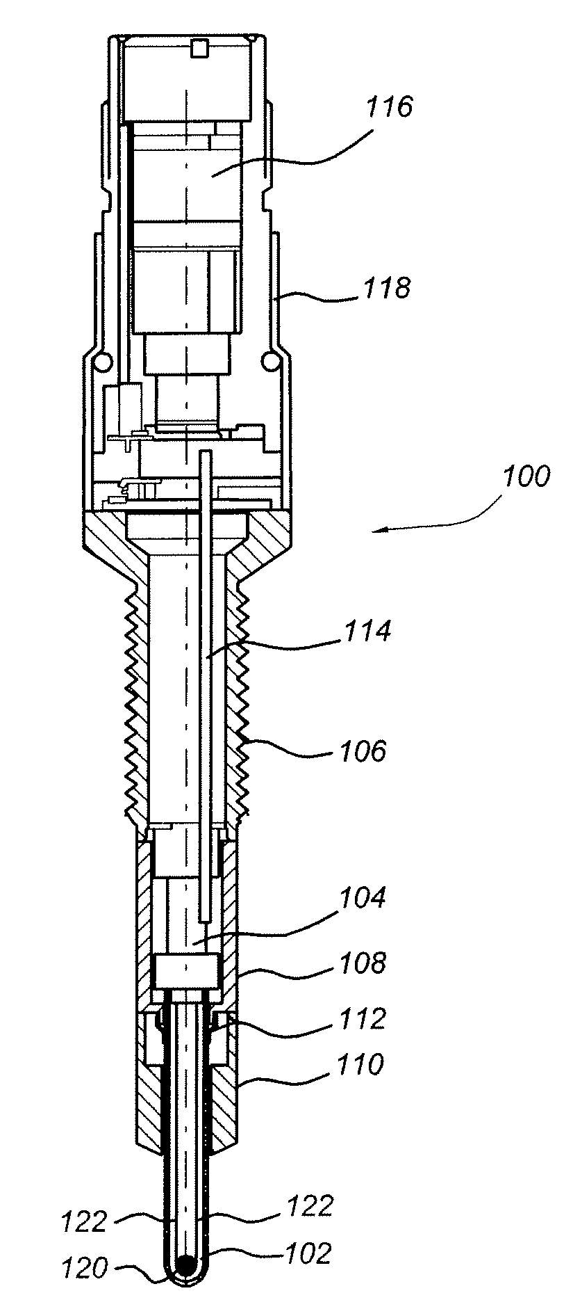
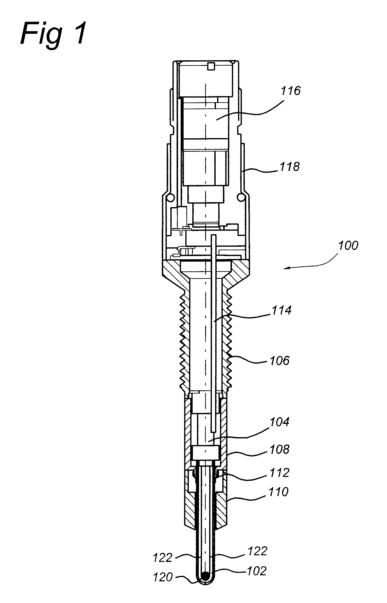
[0034]a pressure-measuring plug 100 according to the invention is shown in FIG. 1. The pressure-measuring plug 100 comprises a rod 102, a plug body 110, 108, 106, a sensing structure 104, a PWB 114 provided with sensor electronics and sensor electrical connections 116. The sensor electrical connections 116 are arranged in a housing 118, which is arranged to seal from the environment the cavity in the plug body 106, 108, 110 wherein the sensing structure 104 and the sensor electronics 114 are located.

[0035]In the example of the embodiment shown in FIG. 1, plug body 110, 108, 106 comprises a body lower part 110, a body middle part 108 and a body upper part 106, which are connected together mechanically. The body lower part 110 is provided on the combustion chamber side with a sealing cone, by means of which the pressure measuring plug seals off the combustion pressure at the cylinder head. The body middle part 108 encompasses the sensing structure 104. The sensor electrical connection...

third embodiment

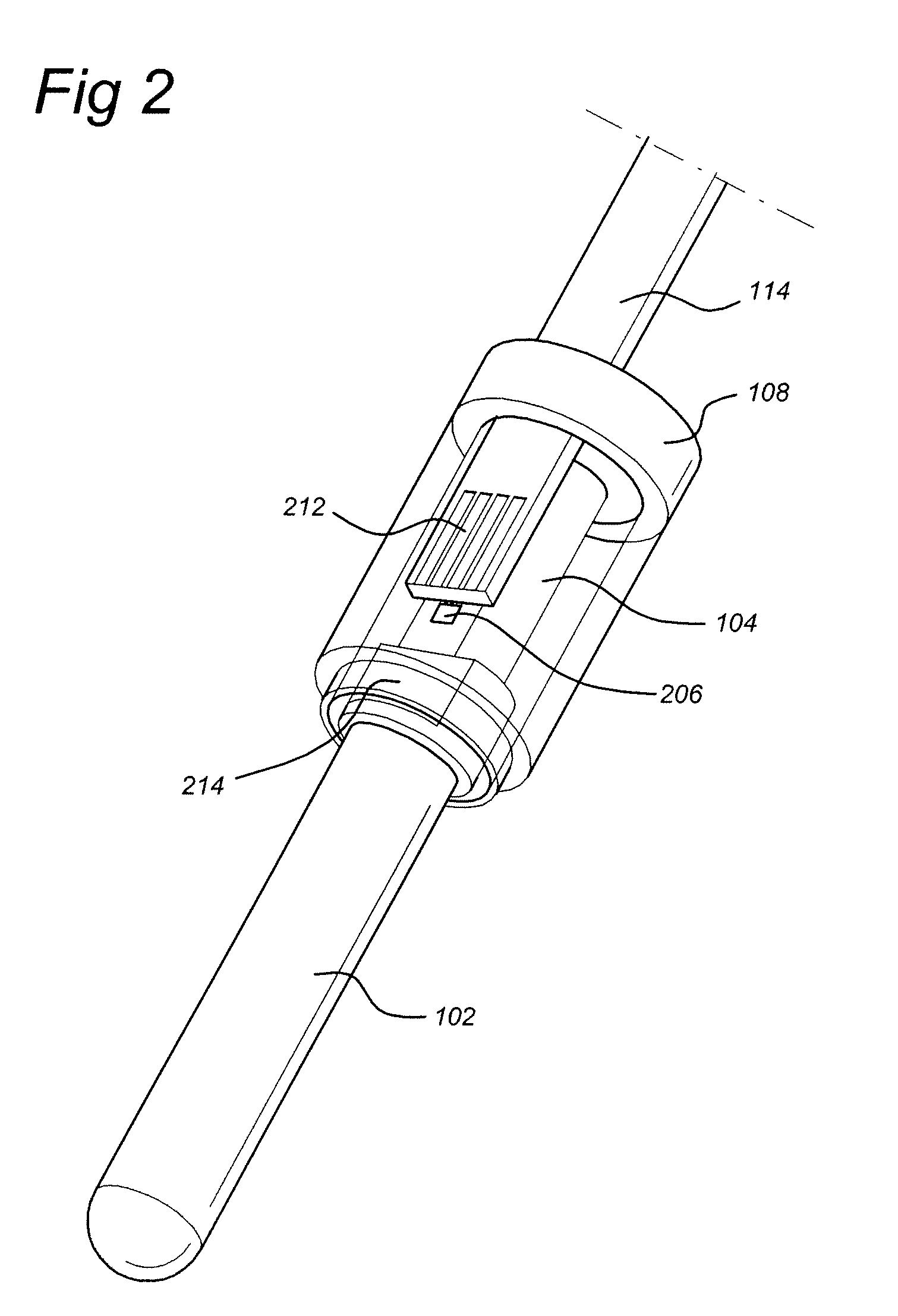
[0055]FIG. 7 shows a perspective view of the invention and FIG. 8 shows an enlarged perspective view of the sensing structure 104a, PWB 114a and rod 102. The body upper part 106 is an elongated body which comprises along a part of its external surface a thread for mounting the sensor arrangement in a combustion engine. A sensing structure 104a is provided in the body middle part 108.

[0056]In this embodiment, the sensing structure 104a is a membrane structure, which transforms an axial movement of the rod 102 in a surface strain in radial direction. The piezoresistive elements 206 mounted on the sensing structure 104a provides a resistance change representing the surface strain in radial direction when the rod 102 is moved in axial direction. EP1790964A1 discloses the working principle of such a membrane structure. In this embodiment the sensing structure 104a is mechanically connected to the body lower part 110. The sensing structure 104a comprises a rim 132 on which a cylindrical e...


PUM

PropertyMeasurementUnit
resonance frequencyaaaaaaaaaa
frequencyaaaaaaaaaa
frequencyaaaaaaaaaa

Abstract

A piezoresistive pressure-measuring plug (100) for a combustion engine for measuring a pressure is disclosed. The piezoresistive pressure-measuring plug (100) comprises:a plug body (106, 108, 110) for insertion into a cylinder of the combustion engine, a rod (102) that is arranged in the plug body (106, 108, 110), a sensing structure (104) comprising a piezoresistive element, that is arranged between the rod (102) and the plug body (106, 108, 110) in such a way that the sensing structure is acted upon, in use, by the pressure prevailing in the combustion chamber of the cylinder, whereby the rod (102) transmits the pressure in the combustion chamber of the cylinder to the sensing structure due to the pressure in the combustion chamber leading to an axial motion of the rod (102) relative to the plug body (106, 108, 110) so as to apply a force to the sensing structure (104) and a PWB (114) provided with sensor electronics for measuring and conditioning a resistance change. The sensing structure (104) is arranged in the plug body (106, 108, 110) and, in use is compressed in axial direction by the force applied to the sensing structure (104) and a piezoresistive element (206) mounted on the sensing structure (104) to provide a resistance change when the sensing structure (104) is compressed in axial direction. Furthermore, the PWB (114) is arranged in the plug body (106, 108, 110). In this way a pressure-measuring plug is obtained with improved bandwidth and reduced build-in height.

Description

FIELD OF THE INVENTION[0001]The invention relates to a pressure-measuring plug for a combustion engine with a plug body for insertion into a cylinder of the combustion engine, a rod which is arranged in the plug body, and a sensing structure, which is arranged between the rod and the plug body in such a way that the sensing structure is acted upon by the pressure prevailing in the combustion chamber of the cylinder, whereby the rod transmits the pressure in the combustion chamber of the cylinder to the sensing structure and in which the rod is arranged in the plug body so as to be displaceable in a sliding manner in the axial direction relative to the plug body, so that the pressure in the combustion chamber leads to an axial motion of the heating rod relative to the plug body, as a result of which motion the sensing structure is acted upon by a force.BACKGROUND OF THE INVENTION[0002]A pressure-measuring plug of the above-mentioned type is known from U.S. Pat. No. 7,228,730 and US 2...

Claims


Application Information

Patent Timeline
Patent Type & Authority Applications(United States)
IPC IPC(8): G01M15/00H04R17/00
CPCG01L23/18Y10T29/42F23Q2007/002F23Q7/001
Inventor BORGERS, MARC GERARD JOHANZWOLLO, CRIS RUIZZWIJZE, ROBERTGENNISSEN, PAULUS THOMAS JOHANNESTIEK, TIMTONEMAN, HUUBGROENHUIJZEN, SERGE
Owner SENSATA TECHNOLOGIES INC
Why Eureka
Try Eureka