Methods and Apparatus for Wireline Drilling On Coiled Tubing

a wireline and wireline technology, applied in the direction of drilling drives, drilling pipes, borehole/well accessories, etc., can solve the problems of low efficiency in the conversion of hydraulic power to drilling footage, limited reach of ct drilling, etc., and achieve the effect of improving the transportation of cuttings

Inactive Publication Date: 2009-12-31
SCHLUMBERGER TECH CORP
View PDF6 Cites 32 Cited by
  • Summary
  • Abstract
  • Description
  • Claims
  • Application Information

AI Technical Summary

Benefits of technology

[0019]In use, the flow diverter can direct part of the drilling fluid down around the outside of the drilling system and the remainder of the fluid back to the surface around the outside of the tubular conveyance. Thus the reverse circulation around the drilling system changes to conventional circulation around the tubular conveyance which allows improved cuttings transport in the main part of the borehole. The flow diverter can be arranged to divert flow from the inside of the drilling system to the annulus above the point at which it diverts flow from the tubular conveyance system into the annulus.

Problems solved by technology

This high drilling power requires a large-diameter CT that demands larger surface installations.
Apart from the larger and heavier surface equipment, this way of drilling on CT is limited in reach by the buckling limit of the CT, and involves a low-efficiency conversion of hydraulic power to drilling footage.

Method used


Image

  • Methods and Apparatus for Wireline Drilling On Coiled Tubing
  • Methods and Apparatus for Wireline Drilling On Coiled Tubing
  • Methods and Apparatus for Wireline Drilling On Coiled Tubing

Examples


Embodiment Construction

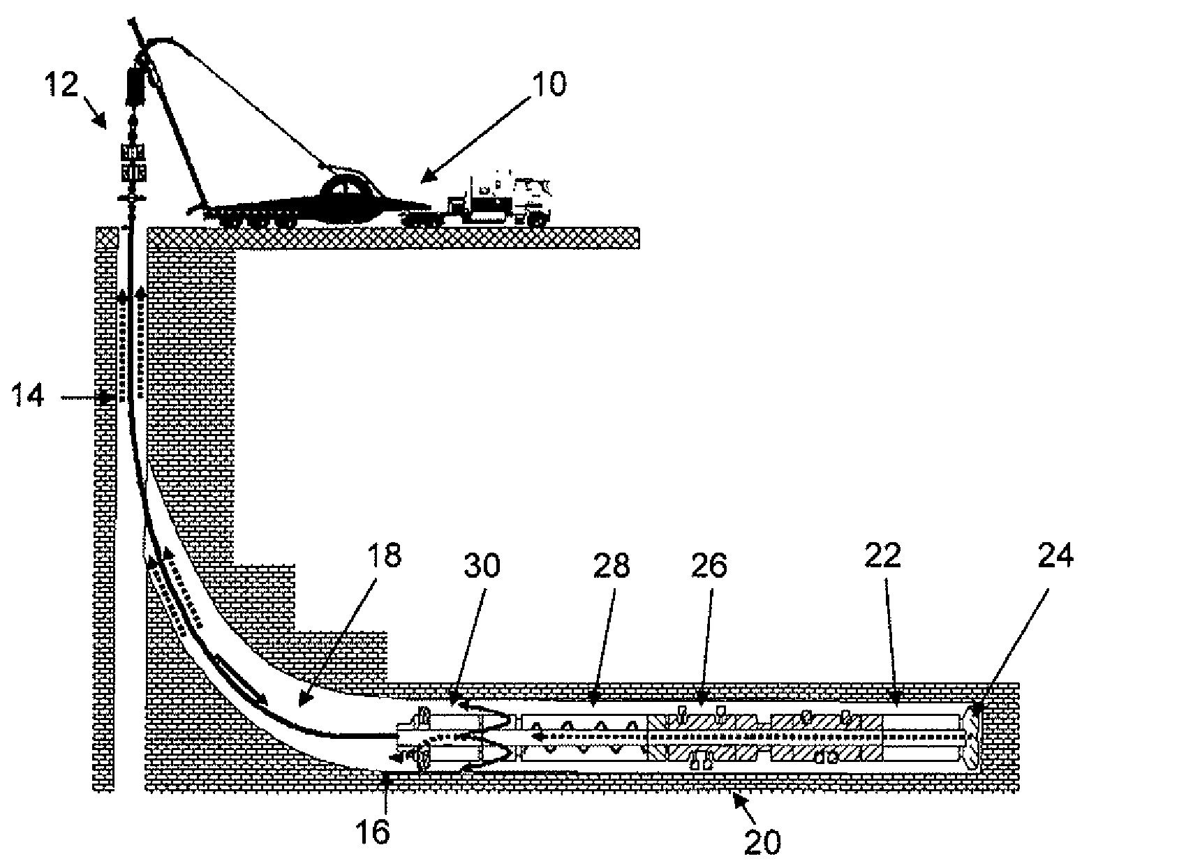
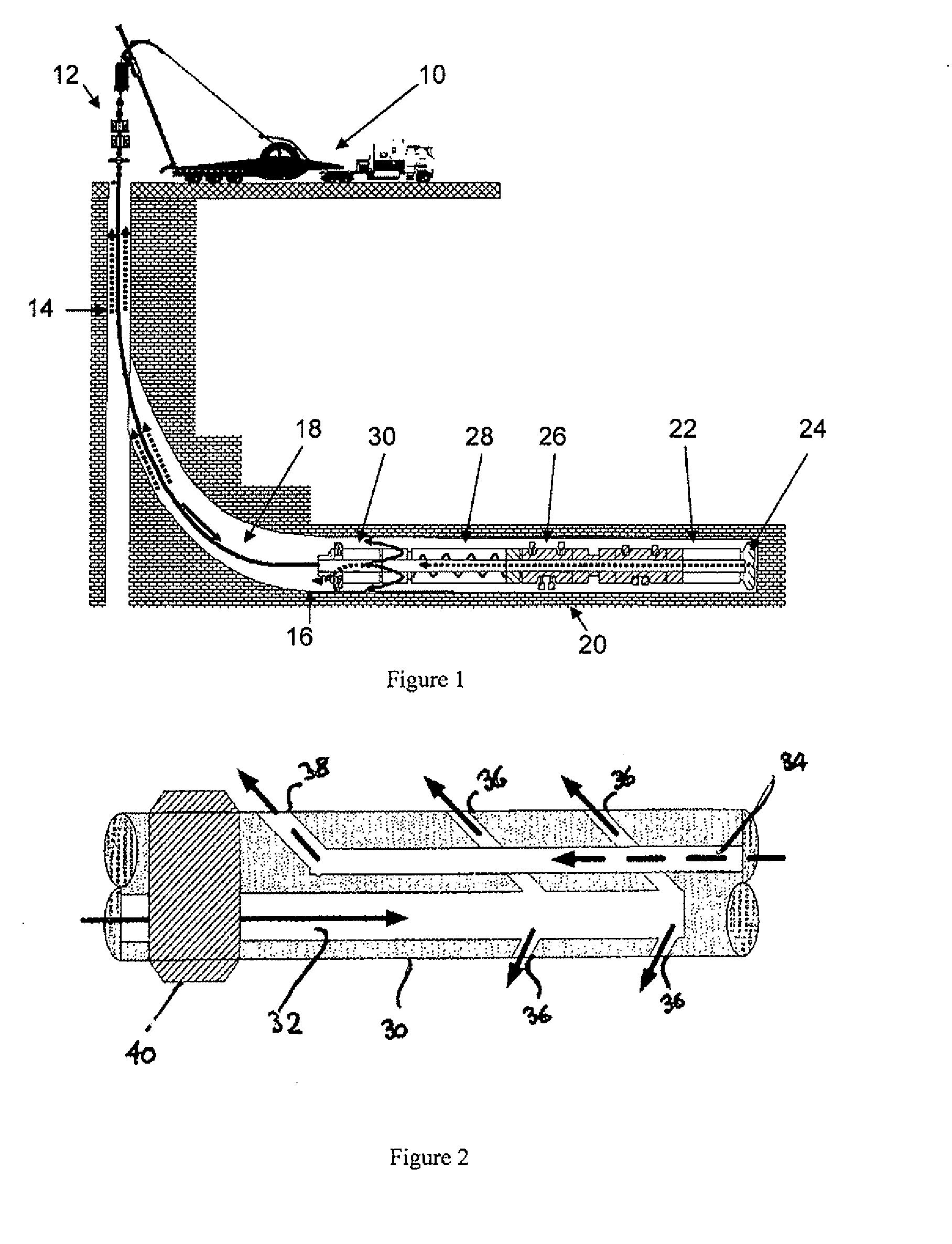
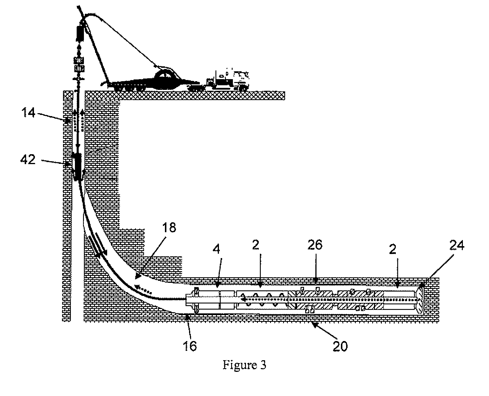
[0036]The drilling operation shown in FIG. 1 is conducted using a conventional CT unit 10 and injector / pressure control setup 12 at the surface of the well 14 and is being used to drill a lateral well 16 extending away from the main well 14. The lateral well 16 has been started in the usual manner by milling a window in the casing and drilling laterally using a whipstock to provide deviation in drilling direction. The drilling apparatus comprises a CT conveyance system 18 carrying a drilling assembly 20 at its lower end. The conveyance system 18 comprises a CT having an electric cable running inside from the surface. The weight of the tool is carried by the CT 18, so the electric cable only needs to be able to support its weight. A drilling fluid supply forms part of the CT unit 10 at the surface and pumps drilling fluid down the inside of the CT.

[0037]The drilling assembly 20 comprises a motor section 22 including an electric motor providing rotary drive to a drill bit 24. Immediat...


PUM


Abstract

Apparatus for drilling an underground borehole, comprising:
    • a tubular conveyance system (18) including an electric cable and a supply of drilling fluid, the supply of drilling fluid being arranged in use to pump fluid from the surface down the inside of the tubular conveyance so as to return to the surface via the annulus between the outside of the tubular conveyance and the borehole;
    • a drilling system comprising an electrically powered pump and a drilling motor, the pump being arranged in use to pump fluid from the borehole outside the drilling system up through the inside of the drilling system;
    • a connector connecting the drilling system to the tubular conveyance system (18), through which the pump and motor are connected to the electric cable, and
    • a flow diverter at which flow down the inside of the tubular conveyance system (18) is diverted into the annulus, and flow up the inside of the drilling system is diverted into the annulus.

Description

TECHNICAL FIELD [0001]This invention relates to methods and apparatus for drilling boreholes that is particularly applicable to drilling with wireline drilling apparatus carried on coiled tubing.BACKGROUND ART [0002]Current conventional coiled tubing drilling (CTD) employs high hydraulic power delivered from the surface through the coiled tubing (CT) to power a drilling positive displacement motor (PDM) that in turn powers the drill bit. This high drilling power requires a large-diameter CT that demands larger surface installations.[0003]Current methods of changing the trajectory in CTD typically involve a fixed bend on the PDM, and a hydraulic or electric-over-hydraulic means of rotating the bend azimuth. Apart from the larger and heavier surface equipment, this way of drilling on CT is limited in reach by the buckling limit of the CT, and involves a low-efficiency conversion of hydraulic power to drilling footage.[0004]U.S. Pat. No. 2,548,616 describes a method of drilling a well ...

Claims


Application Information

Patent Timeline
Patent Type & Authority Applications(United States)
IPC IPC(8): E21B4/00E21B7/00E21B7/18E21B7/02E21B4/04E21B4/02E21B4/16E21B6/00E21B21/00E21B21/12
CPCE21B4/04E21B21/103E21B17/20E21B4/18
Inventor KOTSONIS, SPYROZEMLAK, WARRENCOOPER, IAIN
Owner SCHLUMBERGER TECH CORP
Why Eureka
Try Eureka