Airbag for a motor vehicle

a technology for airbags and motor vehicles, applied in the direction of vehicle components, pedestrian/occupant safety arrangements, vehicular safety arrangments, etc., can solve problems such as blocking passages, and achieve the effect of absorbing higher loads and improving the sealing function

Inactive Publication Date: 2009-12-31
DAIMLER AG
View PDF12 Cites 13 Cited by
  • Summary
  • Abstract
  • Description
  • Claims
  • Application Information

AI Technical Summary

Benefits of technology

[0011]If the gas cushions form a side airbag, advantageously the first gas cushion may be arranged in the chest region and the second gas cushion in a pelvic region of an occupant to be restrained. The advantage of this is that the gas cushion in a pelvic region can absorb higher loads than the gas cushion in the chest region. In one embodiment of the invention, the flow passage is formed by two opposite walls, at least one of which is of double-layer design. The double layer causes a closing of the flow passage in a blocking direction when the internal pressure rises.
[0012]If the double layer is fastened with one side to the wall and the other side is freely movable, when gas flows back, this overlap region is inflated, so that the flow passage is automatically sealed off. The more gastight the material (for example, coated fabric) used in this region is, the better this seal functions. The filling of the chambers with different internal pressures may be implemented, for example, via differently dimensioned inflow cross sections.

Problems solved by technology

If both walls are of double-layer design, a closing of the flow passage in the blocking direction can take place even in the case of unfavorable flow conditions.

Method used


Image

  • Airbag for a motor vehicle
  • Airbag for a motor vehicle

Examples


Embodiment Construction

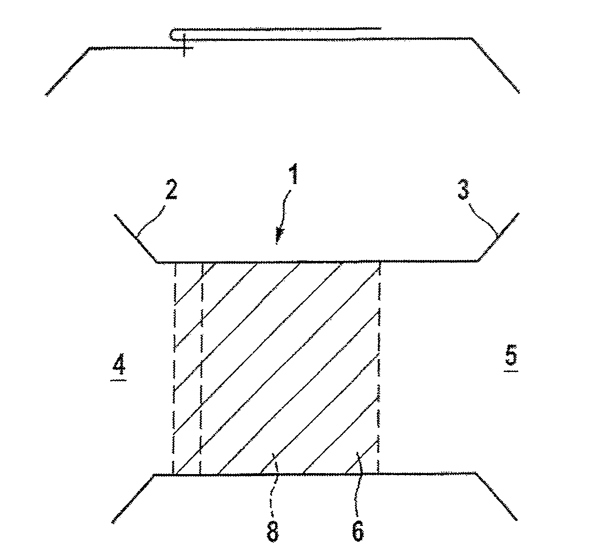
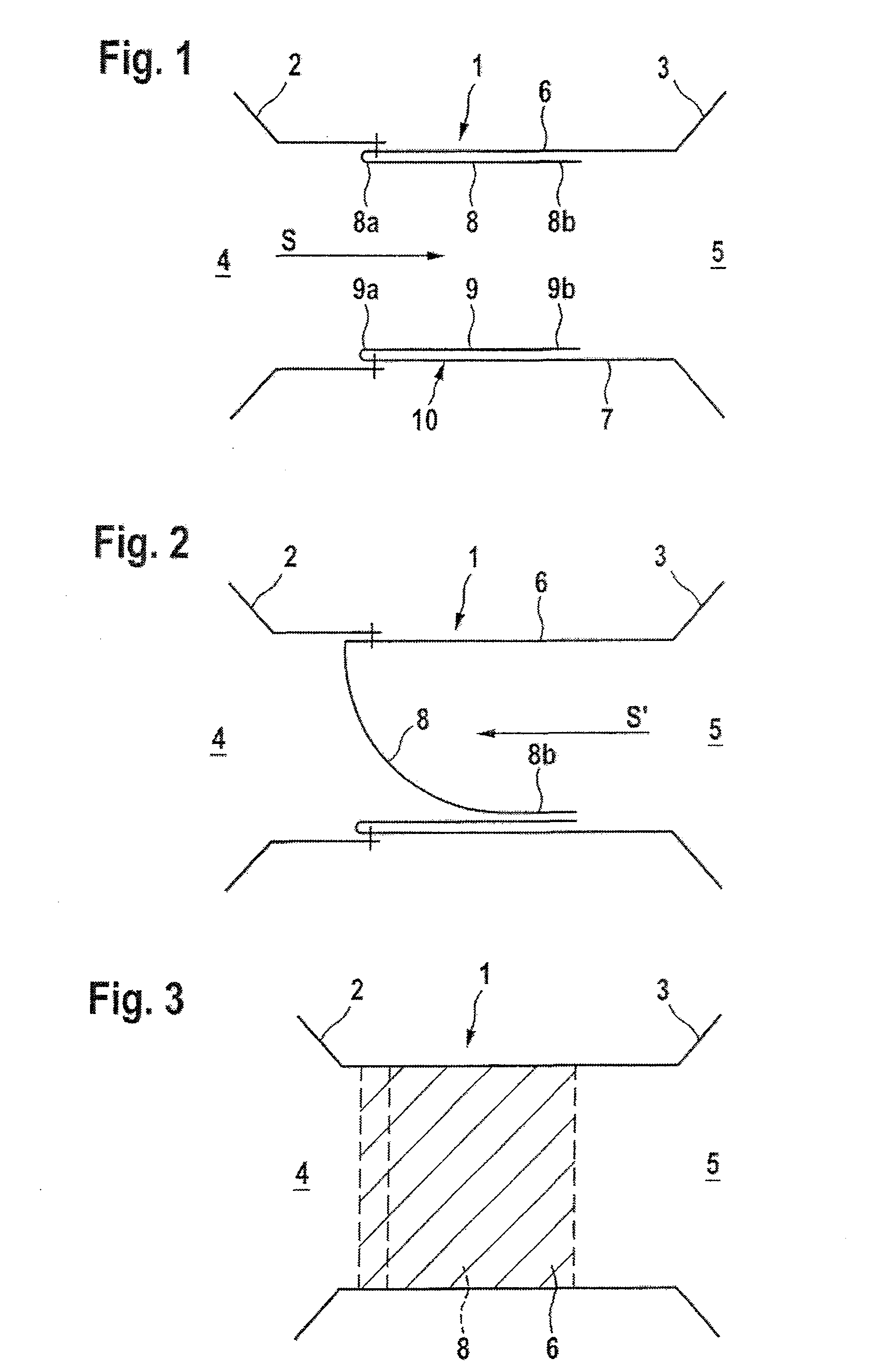
[0018]FIG. 1 illustrates a flow duct 1 which connects two gas cushions 2 and 3, designed as pressure chambers 4 and 5, to one another. The flow duct 1 is formed by two opposite walls 6 and 7 which are double-layer in a part region illustrated by hatching in FIG. 3. For this purpose, the wall 6, 7 is folded around inwardly, thus resulting in a double layer 8, 9. This double layer 8, 9 is consequently fastened with one side 8a, 9a to the wall 6, 7, while the other side 8b, 9b is freely movable. The gas cushion 2 of the pressure chamber 4 is fastened to the wall 6, 7 at the transitional region between the wall 6, 7 and the layer 8, 9. If, therefore, the inflow of the gas occurs from the pressure chamber 4 into the pressure chamber 5 via the flow duct 1 in the direction of the arrow S, the double layers 8, 9 are pressed on to the walls 6, 7. The gas stream can flow, unimpeded, in the passage direction S into the pressure chamber 5.

[0019]Looking at FIG. 2, it becomes clear how the backfl...


PUM


Abstract

In an airbag for a motor vehicle, with a flow passage via which two pressure chambers are connected to one another, a flow medium, in particular gas, flows from one pressure chamber through the flow passage into the other pressure chamber in a passage direction. To increase the suitability of the airbag for, for example, side impact loads, the flow passage includes a backflow safeguard that allows the flow medium to flow in the passage direction, whereas the flow of the flow medium in a blocking direction opposite to the passage direction is largely prevented.

Description

BACKGROUND AND SUMMARY OF THE INVENTION[0001]This invention relates to an airbag for a motor vehicle.[0002]In passive restraint systems, airbags that are filled with gas abruptly in the event of an accident in order to restrain an occupant have become known. Airbags of this type are used both as a driver or front-seat passenger airbag in the case of a front collision and a window or side bag in the case of a side collision. It is known, furthermore, that the internal pressure of the airbag can be regulated, by various measures, in order to implement inflation with a high or a lower internal pressure as a function of load-relevant parameters.[0003]German document DE 101 11 566 A1, for example, shows an airbag for a motor vehicle with an outflow orifice, which in the broadest sense forms a flow passage. This flow passage connects two pressure chambers, to be precise the inner space of the airbag and the space around the airbag, to one another. In the event of an abrupt inflation of th...

Claims


Application Information

Patent Timeline
Patent Type & Authority Applications(United States)
IPC IPC(8): B60R21/16
CPCB60R21/239
Inventor BAUER, GEORGRUEDEBUSCH, CLARK
Owner DAIMLER AG
Why Eureka
Try Eureka