Unlock instant, AI-driven research and patent intelligence for your innovation.

System and method for performing ultracapacitor cell balancing

a technology of ultracapacitor and cell, applied in the field of ultracapacitors, can solve the problems of poor system operation or failure, open cell, and easy voltage breakdown of nanoporous materials, and achieve the effects of improving the efficiency of the system

Inactive Publication Date: 2009-12-31
EATON INTELLIGENT POWER LTD
View PDF3 Cites 5 Cited by
  • Summary
  • Abstract
  • Description
  • Claims
  • Application Information

AI Technical Summary

Benefits of technology

The present invention provides a system and method for balancing a sub-set of ultracapacitors within a stack of ultracapacitors that overcomes the aforementioned drawbacks. The technical effects of the invention include reducing voltage imbalances in a stack of ultracapacitors, improving the efficiency of the overall system, and increasing the reliability of the system.

Problems solved by technology

The nanoporous material is susceptible to voltage breakdown and is thus limited, typically, to operating voltages in the range of 2-3 volts.
However, such extremes are detrimental to the life of the ultracapacitor and failure may occur, which may result in an open cell.
However, due to temperature gradients and manufacturing irregularities, imbalance can occur between the cells which can lead to poor system operation or failure due to overvoltage of one or more of the ultracapacitors within the stack.
However, such life is negatively affected by operating at overvoltage, and actual life can be based on a prorated or percentage time spent operating at the elevated voltage or temperature.
Further, fully failed cells cause an open of the cell, thus preventing all others within a string or sub-stack from delivering power, which drops energy storage as the square of the voltage, reducing storage and performance.
Though these solutions may offer improvements for some systems, they introduce tradeoffs as well.
Active and individual cell balancing may be effective, but adds cost—both in complexity to the system design and complexity of operation.

Method used


Image

  • System and method for performing ultracapacitor cell balancing
  • System and method for performing ultracapacitor cell balancing
  • System and method for performing ultracapacitor cell balancing

Examples


Embodiment Construction

[0019]The embodiments of the invention set forth herein relate to a system and method of balancing a voltage across a sub-set of ultracapacitors within a series of ultracapacitors.

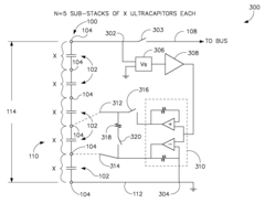
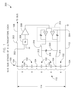
[0020]FIG. 1 illustrates a circuit 300 for balancing ultracapacitors according to an embodiment of the invention. Circuit 300 is coupled to a stack of ultracapacitors 100 that is divided into sub-stacks 102 of ultracapacitor cells. Each sub-stack 102 of ultracapacitors is separated by a pair of electrical nodes 104. FIG. 1 illustrates N sub-stacks 102 of X ultracapacitor cells in each sub-stack 102. Thus, in the example illustrated, there are N=5 sub-stacks 102 of X ultracapacitors.

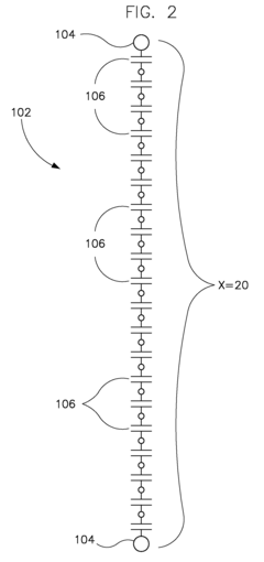
[0021]Referring now to FIG. 2, a single sub-stack 102 of X=20 ultracapacitor cells 106 is illustrated as an example according to an embodiment of the invention. Further, in this example, each ultracapacitor cell 106 has a capacity to hold a voltage of 2.5 V. Accordingly, for a sub-stack 102 of twenty charged ultracapacitor cells...


PUM


Abstract

A circuit for balancing a sub-stack voltage in a stack of ultracapacitors includes a pair of electrical leads that are connectable across a first sub-stack of one or more ultracapacitors, wherein a stack includes N sub-stacks of ultracapacitors coupled to an electrical bus, a discharge device switchably connectable with the pair of electrical leads, the discharge device configured to discharge the sub-stack of ultracapacitors, a voltage sensing circuit coupled to the electrical bus and configured to sense and output a voltage of the stack of ultracapacitors after the first sub-stack of one or more ultracapacitors has been discharged to a given threshold, and a voltage amplifier coupled to the output of the voltage sensing circuit and coupled to the pair of electrical leads, the voltage amplifier configured to provide a re-charge voltage to the first sub-stack of one or more ultracapacitors.

Description

CROSS-REFERENCE TO RELATED APPLICATION[0001]The present application is a non-provisional of, and claims priority to, U.S. Provisional Application 61 / 133,539 filed Jun. 30, 2008, which is incorporated herein by reference.BACKGROUND OF THE INVENTION[0002]The invention relates generally to ultracapacitors and, more particularly, to a system and method for performing ultracapacitor cell balancing.[0003]Ultracapacitors, also known as supercapacitors, are electrochemical capacitors that have a high energy density as compared to common capacitors. Typically a capacitance of an ultracapacitor is on the order of thousands of times greater than a conventional electrolytic capacitor. In contrast to conventional capacitors, ultracapacitors typically use plates that are two layers of the same substrate that form an electrical double layer. The plates are typically separated by a nanoporous material such as activated charcoal that allows the separation to be in the nanometer range. Because of the...

Claims


Application Information

Patent Timeline
Patent Type & Authority Applications(United States)
IPC IPC(8): H02J7/00
CPCG01R19/0084H02J7/345H02J7/0016
Inventor ZUERCHER, JOSEPH CHARLES
Owner EATON INTELLIGENT POWER LTD