Resistance measuring apparatus

a technology of resistance and measuring equipment, applied in the direction of resistance/reactance/impedence, earth resistance measurement, instruments, etc., can solve the problems of large precision drop, high manufacturing cost, and high precision loss, and achieve sufficient detection gain, remove such normal-mode noise, and reduce manufacturing costs

Active Publication Date: 2009-12-31
HIOKI DENKI KK
View PDF23 Cites 38 Cited by
  • Summary
  • Abstract
  • Description
  • Claims
  • Application Information

AI Technical Summary

Benefits of technology

[0006]Secondly, with this resistance measuring apparatus, since the injection coil and the detection coil are clipped onto the measured network by carrying out separate operations, it is always necessary to carry out two clipping operations, resulting in the problem that measurement operations are troublesome. There is a further problem in that since there are fluctuations in the clipped-on positions of both coils onto the measured network, the relative positions of both coils are not stable and the conditions during measuring become unstable. To solve such problems, the present inventor has already developed a new resistance measuring apparatus that can make the clipping operation more efficient and can stabilize the relative positions of the coils by adapting the resistance measuring apparatus described above to a construction where the injection coil and the detection coil are enclosed in a single clamp-type housing.
[0048]With the above construction, since it is possible to avoid the use of a single-ended detection coil and the use of a shunt resistor, it is possible to achieve favorable frequency characteristics while maintaining a sufficient detection gain. Also, since the first amplifier unit and the second amplifier unit that are connected to the respective ends of the detection coil output the first voltage signal and the second voltage signal with respectively opposite phase based on the current flowing in the detection coil, and the differential amplifier unit outputs the difference signal on a difference between the positive polarity signal and the negative polarity signal generated by the extraction units based on such signals, even if common-mode noise is superimposed on the current flowing in the detection coil, it will still be possible to cancel the common-mode noise in the differential amplifier unit. Also, since the extraction units carry out synchronous detection on the first and second voltage signals in synchronization with the reference signal and extract the positive polarity signal and the negative polarity signal, even if normal-mode noise is included in the current in the detection coil, it will still be possible to remove such normal-mode noise.

Problems solved by technology

However, by investigating the resistance measuring apparatus described above, the present inventor found the problem described below with the resistance measuring apparatus.
In this case, although it is necessary to construct the frequency selecting circuit using a band-pass filter with a steep slope (i.e., a high Q band-pass filter) to extract the second frequency component with high precision, it will be necessary to use high-precision components to realize such a frequency selecting circuit, and since such high-precision components are normally expensive, there is the problem of a rise in the manufacturing cost.
Also, although the center frequency of a band-pass filter will unavoidably shift due to the influence of peripheral temperature, with a high Q band-pass filter, a shift in the center frequency has an extremely large effect, and therefore there is the risk that the shift in center frequency will cause a large fall in precision.
Secondly, with this resistance measuring apparatus, since the injection coil and the detection coil are clipped onto the measured network by carrying out separate operations, it is always necessary to carry out two clipping operations, resulting in the problem that measurement operations are troublesome.
There is a further problem in that since there are fluctuations in the clipped-on positions of both coils onto the measured network, the relative positions of both coils are not stable and the conditions during measuring become unstable.
With the conventional resistance measuring apparatus described above, although the frequency selecting circuit removes unnecessary frequency components from the output of the detection transformer (detection coil) and extracts the second frequency component, since the frequency component generated in the detection coil due to the detection coil being encircled by the magnetic field generated by the injection coil is the same frequency component injected by the injection coil (i.e., the second frequency component), it is not possible to remove such component using the frequency selecting circuit, resulting in the problem that it is difficult to achieve a suitable measurement precision.
However, in a construction that uses DC amplification, there is the problem of deterioration in the dynamic reserve and a reduction in noise tolerance.
Also, although it is necessary to use an amplifier with a small offset as the operational amplifier that constructs the rectifying amplification circuit, since such operational amplifiers are expensive, there is also the problem that this brings about a rise in the manufacturing cost.

Method used


Image

  • Resistance measuring apparatus
  • Resistance measuring apparatus
  • Resistance measuring apparatus

Examples


Embodiment Construction

[0077]Preferred embodiments of a resistance measuring apparatus according to the present invention will now be described with reference to the attached drawings.

[0078]First, the construction of a resistance measuring apparatus 1 will be described with reference to the drawings as a first and second resistance measuring apparatus according to the present invention.

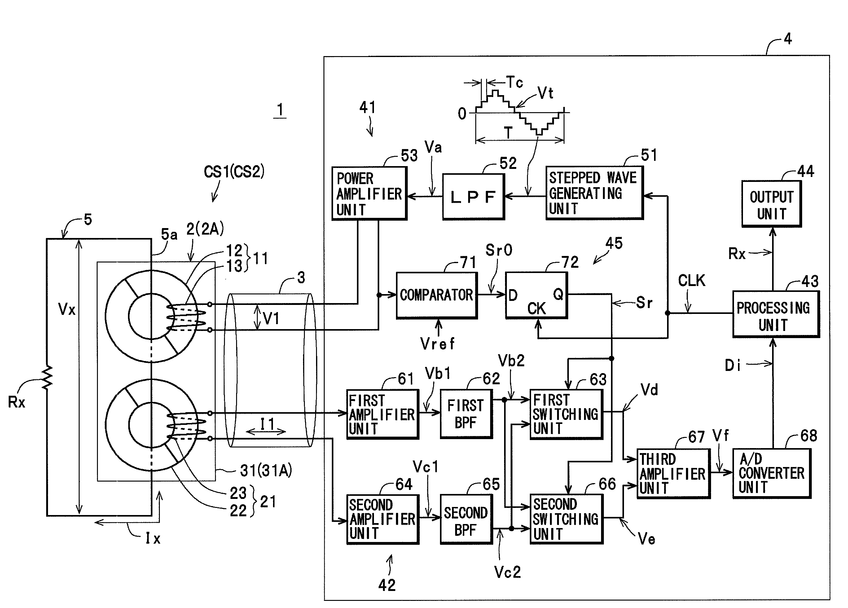
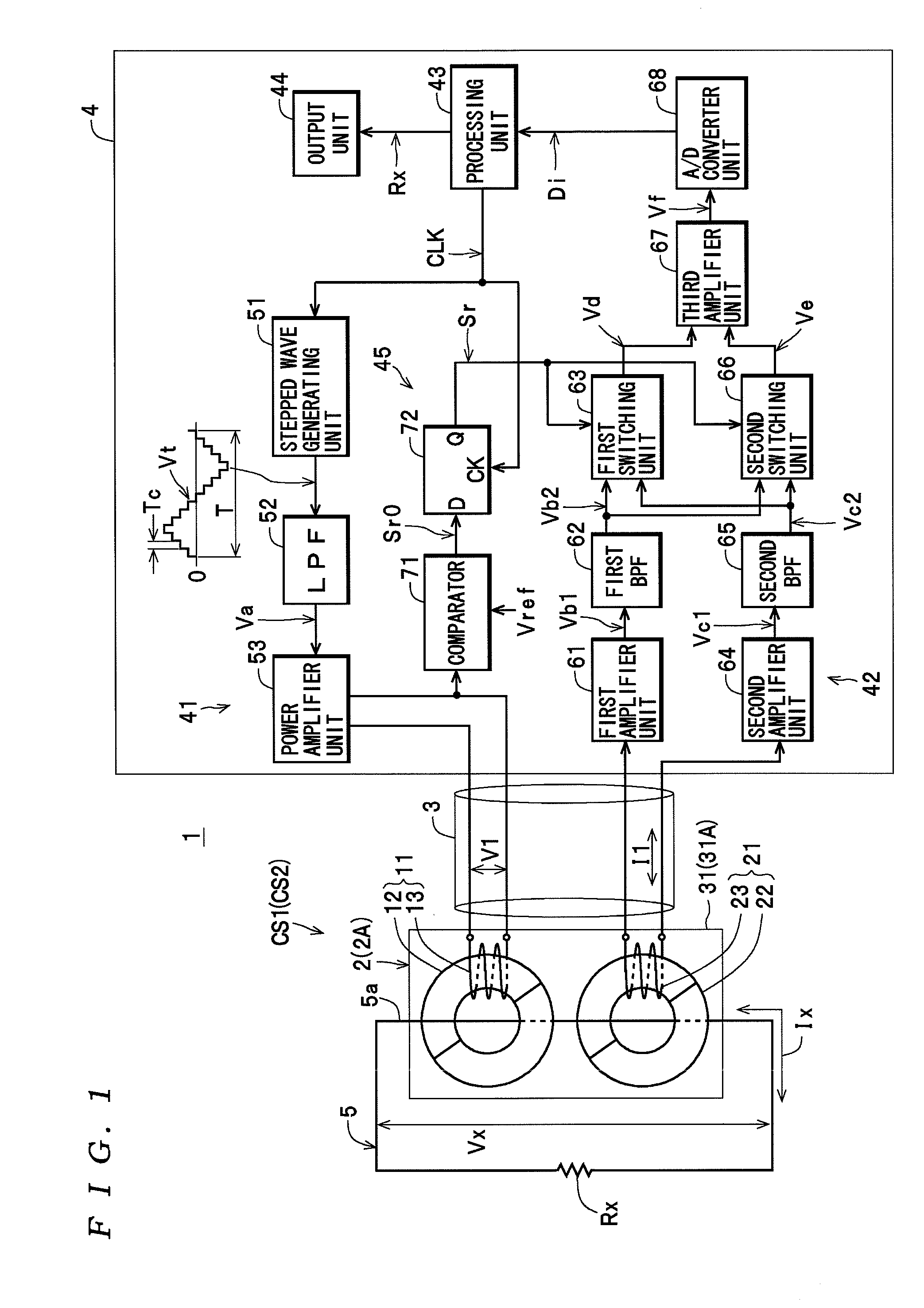
[0079]The resistance measuring apparatus 1 shown in FIG. 1 includes a clamp sensor CS1, and an apparatus main unit 4 connected to the clamp sensor CS1 via a cable 3, and is constructed so as to be capable of measuring the resistance value Rx for the resistance (i.e., loop resistance) of a measured circuit 5.

[0080]As shown in FIG. 10, as one example the clamp sensor CS1 includes a clamp unit 2 that clamps onto the measured circuit 5 and a grip portion 6 that holds the clamp unit 2 so that the clamp unit 2 is freely openable and closable. As shown in FIGS. 1, 10, and 11, the clamp unit 2 includes an injection clamp unit 11, a...


PUM


Abstract

A resistance measuring apparatus includes: a voltage injector that injects an AC signal into a circuit by applying an AC voltage to an injection coil; a current measuring unit that measures an AC current produced in the circuit by the injection coil using a detection coil; a processing unit that calculates the circuit resistance from the AC signal voltage and the measured AC current; and a reference signal generator that outputs a binary reference signal that has a same period as the AC voltage and is synchronized to the clock. The voltage injector generates a stepped wave whose amplitude changes in synchronization with a clock, applies a signal based thereon as the AC voltage. The current measuring unit converts the current in the detection coil to a voltage signal, carries out synchronous detection using the reference signal, and measures the AC current based on the synchronous detection result.

Description

BACKGROUND OF THE INVENTION[0001]1. Field of the Invention[0002]The present invention relates to a resistance measuring apparatus that measures the resistance of a circuit to be measured.[0003]2. Description of the Related Art[0004]As one example of this type of resistance measuring apparatus, the resistance measuring apparatus disclosed in Japanese Examined Patent Application Publication No. H02-7031 (see Paragraphs 1 to 4 and FIG. 2) is known. This resistance measuring apparatus includes an injection transformer that is clipped onto a connecting lead of a measured network and injects a current of a second frequency, which can be discriminated from a current of a first frequency that flows in the measured network (“measured object”), into the measured network, a detection transformer (“detection coil”) that is clipped onto the connecting lead and detects the above two types of current flowing in the measured network, a frequency selecting circuit (more specifically, a frequency-sel...

Claims


Application Information

Patent Timeline
Patent Type & Authority Applications(United States)
IPC IPC(8): G01R27/08
CPCG01R27/20G01R27/02
Inventor IMAIZUMI, SATOSHI
Owner HIOKI DENKI KK
Why Eureka
Try Eureka