Indicator apparatus for hybrid vehicle, hybrid vehicle, indicating method for hybrid vehicle

a hybrid vehicle and indicating device technology, applied in the direction of engine-driven generator propulsion, electric propulsion mounting, transportation and packaging, etc., can solve the problems of driver discomfort, driver discomfort, and driver discomfort, and achieve the effect of reducing the risk of accidents

Active Publication Date: 2009-12-31
TOYOTA JIDOSHA KK
View PDF28 Cites 80 Cited by
  • Summary
  • Abstract
  • Description
  • Claims
  • Application Information

AI Technical Summary

Benefits of technology

[0018]Preferably, the hybrid vehicle includes a switch for allowing the driver to select traveling in the first mode. When the switch is operated by the driver, the control portion changes a threshold value for switching the traveling modes so that a range in which traveling is performed in the first mode is increased. The second indicator portion changes the second state amount in accordance with the change of the threshold value for switching.
[0024]Therefore, according to the present invention, a traveling mode switching point can be indicated to the driver. As a result, the driver can be saved from feeling discomfort when the internal combustion engine is started. Additionally, the driver who wishes to continue traveling in the first mode is allowed to travel in the first mode while recognizing the switching point from the first mode to the second mode. That is, since the driver can intentionally avoid switching from the first mode to the second mode, the environmentally-friendly driving can be achieved.

Problems solved by technology

However, with the hybrid vehicle disclosed by Japanese Patent Laying-Open No. 2001-112112, the driver cannot recognize in advance the timing for switching from EV mode to HV mode, and therefore, the driver may feel discomfort about the abrupt starting of the engine.
In particular, it is expected that the driver is likely to feel such discomfort with a hybrid vehicle in which a power storage apparatus is chargeable from a power supply external to the vehicle (such as from a system power supply).
Accordingly, the driver is likely to feel discomfort when EV mode is switched to HV mode.

Method used


Image

  • Indicator apparatus for hybrid vehicle, hybrid vehicle, indicating method for hybrid vehicle
  • Indicator apparatus for hybrid vehicle, hybrid vehicle, indicating method for hybrid vehicle
  • Indicator apparatus for hybrid vehicle, hybrid vehicle, indicating method for hybrid vehicle

Examples


first embodiment

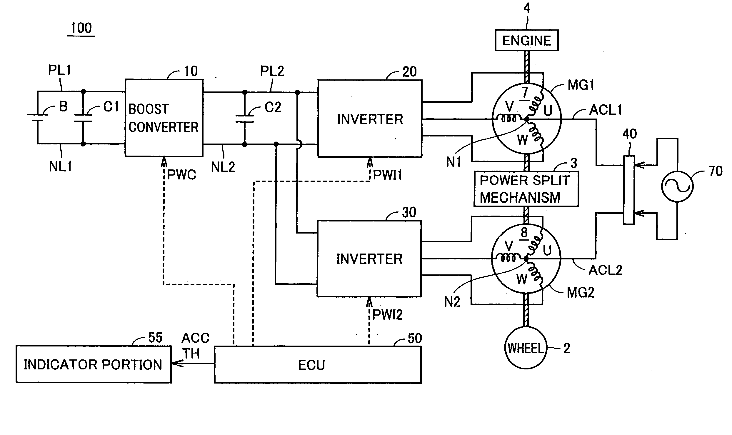
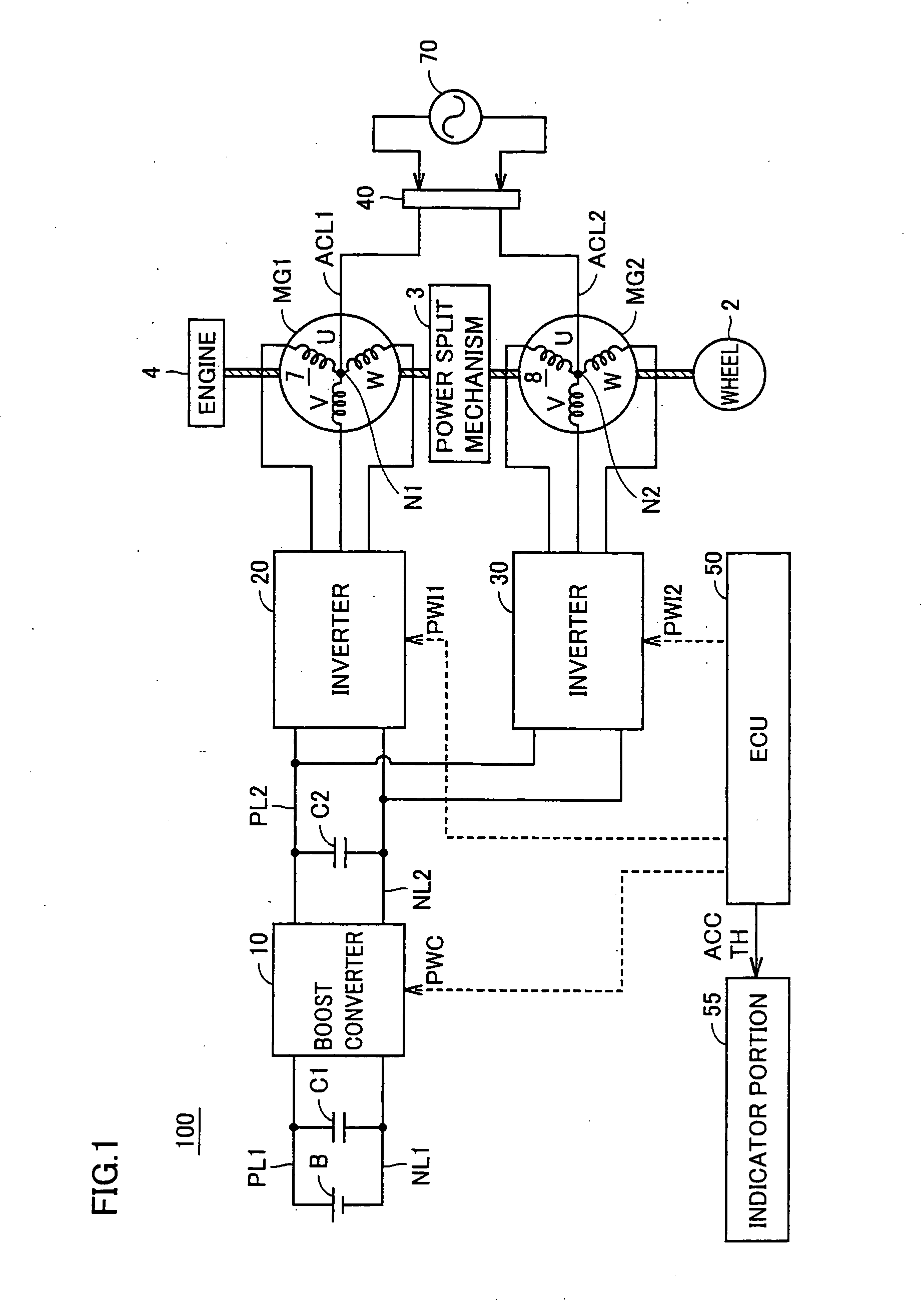
[0049]FIG. 1 is an overall block diagram showing a powertrain of a hybrid vehicle according to a first embodiment of the present invention. Referring to FIG. 1, hybrid vehicle 100 includes an engine 4, motor-generators MG1, MG2, a power split mechanism 3, and wheels 2. Hybrid vehicle 100 further includes a power storage apparatus B, a boost converter 10, inverters 20, 30, a charge connector 40, an ECU (Electronic Control Unit) 50, an indicator portion 55, capacitors C1, C2, positive electrode lines PL1, PL2, and negative electrode lines NL1, NL2.

[0050]Power split mechanism 3 is linked to engine 4 and motor-generators MG1, MG2 for distributing motive power among them. For example, as power split mechanism 3, a planetary gear having three rotation shafts of a sun gear, a planetary carrier, and a ring gear can be used. These three rotation shafts are connected to the rotation shafts of engine 4 and motor-generators MG1, MG2, respectively. For example, by inserting the crankshaft of eng...

second embodiment

[0110]In a second embodiment, when each output of power storage apparatus B, boost converter 10, inverters 20, 30 (in the following, boost converter 10 and inverters 20, 30 are also collectively referred to as “a power control unit (PCU)”), and motor-generators MG1, MG2 is limited due to an increase in the apparatus temperature or any other factor, a threshold value for switching traveling mode is corrected so that the HV mode traveling range is increased. In accordance with the correction of the threshold value for switching, a traveling mode switching point indicated on the indicator portion is also changed. That is, in the second embodiment, when the output is restricted, the traveling mode switching point that is indicated on the indicator portion is also changed accordingly.

[0111]The overall configuration of the powertrain of the hybrid vehicle in the second embodiment is the same as hybrid vehicle 100 in the first embodiment shown in FIG. 1.

[0112]FIG. 15 is a functional block ...

third embodiment

[0124]Irrespective of the driver's accelerator pedal operation, engine 4 may be started based on a demand from the system side. In a third embodiment, when engine 4 is started based on a demand from the system side, that is, when traveling mode is switched from EV mode to HV mode based on a demand from the system side, the indicating state of indicator portion 55 is also appropriately changed accordingly.

[0125]The overall configuration of the powertrain of the hybrid vehicle in the third embodiment is the same as hybrid vehicle 100 in the first embodiment shown in FIG. 1.

[0126]FIG. 19 is a functional block diagram of an ECU in the third embodiment. Referring to FIG. 19, an ECU 50B in the third embodiment includes, as compared with the configuration of ECU 50 in the first embodiment shown in FIG. 3, a traveling mode control portion 90B in place of traveling mode control portion 90.

[0127]Traveling mode control portion 90B receives a signal EGST from a not-shown vehicle ECU. Signal EGS...


PUM


Abstract

An indicator portion (55) includes a first indicator portion (110) and a second indicator portion (112). The first indicator portion (110) indicates an accelerator pedal opening degree that changes in accordance with an operated amount of the accelerator pedal by the driver. The second indicator portion (112) includes a division line (114) and regions (116, 118) divided by the division line (114). The division line (114) shows an accelerator pedal opening degree where traveling modes (EV mode and HV mode) are switched. The regions (116, 118) show the ranges of accelerator pedal opening degrees where traveling is performed in EV mode and HV mode, respectively.

Description

TECHNICAL FIELD[0001]The present invention relates to an indication technique for a hybrid vehicle incorporating an internal combustion engine and an electric motor as motive power sources.BACKGROUND ART[0002]In recent years, hybrid vehicles are receiving widespread attention as environmentally friendly vehicles. As motive power sources, the hybrid vehicles incorporate, in addition to a conventional engine, a power storage apparatus, an inverter, and a motor driven by the inverter.[0003]Among such hybrid vehicles, the vehicles capable of traveling while switching between a traveling mode where traveling is performed only by the motor without starting the engine (hereinafter also referred to as “EV mode”) and a traveling mode where traveling is performed by both the engine and the motor (hereinafter also referred to as “HV mode”) are known.[0004]For example, Japanese Patent Laying-Open No. 2001-112112 discloses a hybrid vehicle that switches between such traveling modes in accordance...

Claims


Application Information

Patent Timeline
Patent Type & Authority Applications(United States)
IPC IPC(8): B60Q1/00B60K6/00B60L50/16
CPCB60K1/02Y02T10/70B60K6/445B60K35/00B60L11/14B60L2240/421B60L2240/423B60L2240/441B60L2240/486B60L2250/16B60W10/06B60W10/08B60W20/00B60W2050/146B60W2510/0638B60W2510/081B60W2510/1005B60W2510/244B60W2540/10B60W2710/083B60W2710/105B60Y2200/90Y02T10/6286Y02T10/642Y02T10/7077Y02T10/6239B60W20/20B60W20/40Y10S903/903B60K6/365B60L50/16Y02T10/62Y02T10/64Y02T10/7072B60K6/442B60W20/10B60W30/182B60W50/14
Inventor SUZUKI, NAOTONAKASHIMA, MOTOHIRO
Owner TOYOTA JIDOSHA KK
Why Eureka
Try Eureka