Time-to-digital conversion with delay contribution determination of delay elements

a time-to-digital conversion and contribution determination technology, applied in the field of time-to-digital converter and a time-to-digital conversion method, can solve the problems of monotonous relation, non-monotonic relation, definite relation, etc., and achieve the effect of excellent precision and linearity of time-to-digital conversion and short delay tim

Active Publication Date: 2009-12-31
ADVANTEST CORP
View PDF6 Cites 20 Cited by
  • Summary
  • Abstract
  • Description
  • Claims
  • Application Information

AI Technical Summary

Benefits of technology

[0014]In an embodiment a relation between the time interval to be converted and the position at which the second pulse catches-up the first pulse is established. Due to variations in the delay time of individual delay elements it is possible that—against the general rule—a particular delay element in the first chain has a shorter delay time than the corresponding delay element in the second chain. This can result in non-monotonicity of the relation between time interval and catch-up position. In an embodiment the particular delay element is detected at which the pulse in the second chain catches-up the pulse in the first chain for the first time and / or for the last time and said relation is established accordingly. This results in a definite, monotonous relation. In an embodiment the calibration described above can be applied to such monotonous Vernier delay line resulting in excellent precision and linearity of time-to-digital conversion.

Problems solved by technology

This can result in non-monotonicity of the relation between time interval and catch-up position.
This results in a definite, monotonous relation.

Method used


Image

  • Time-to-digital conversion with delay contribution determination of delay elements
  • Time-to-digital conversion with delay contribution determination of delay elements
  • Time-to-digital conversion with delay contribution determination of delay elements

Examples


Embodiment Construction

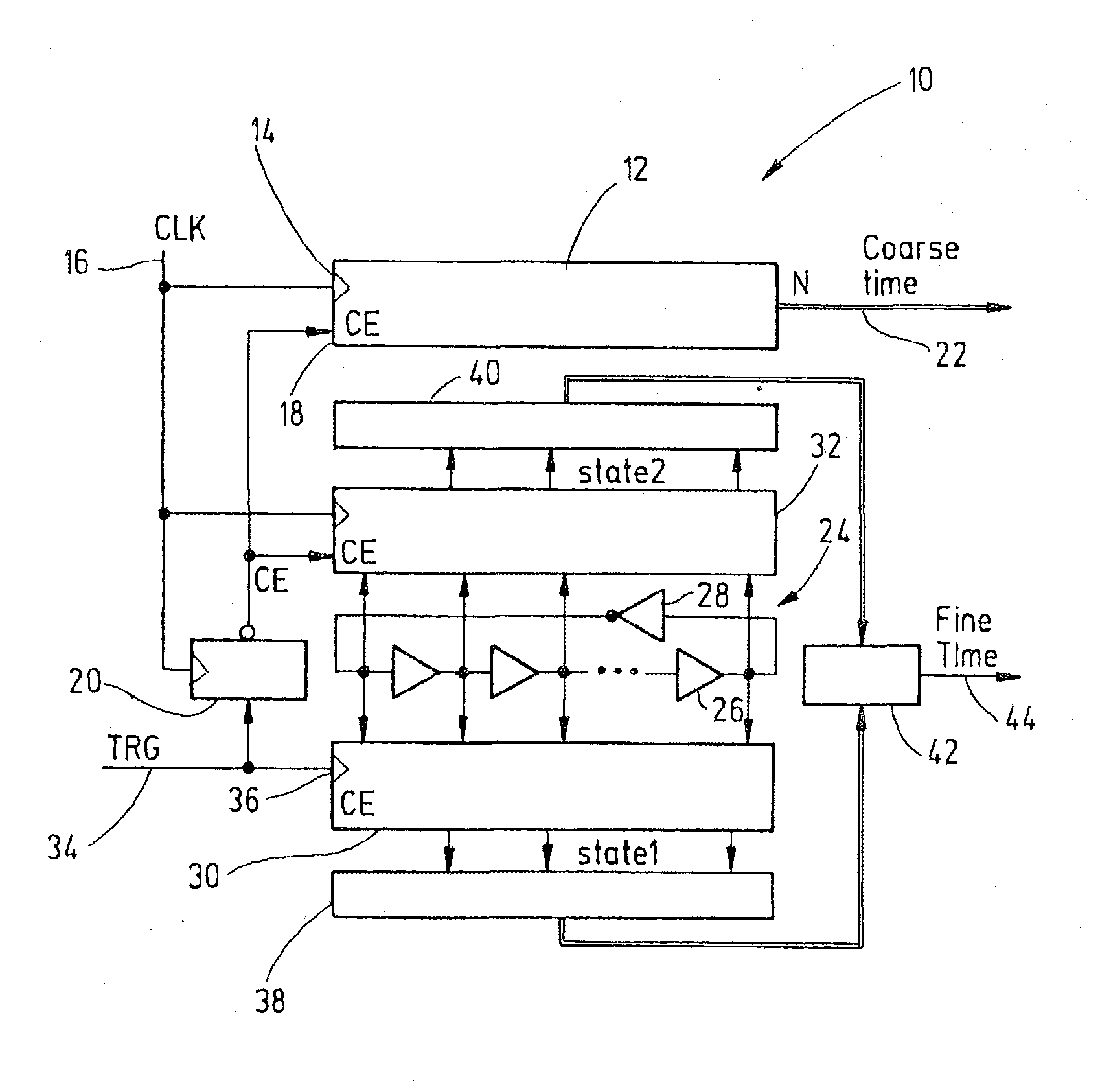
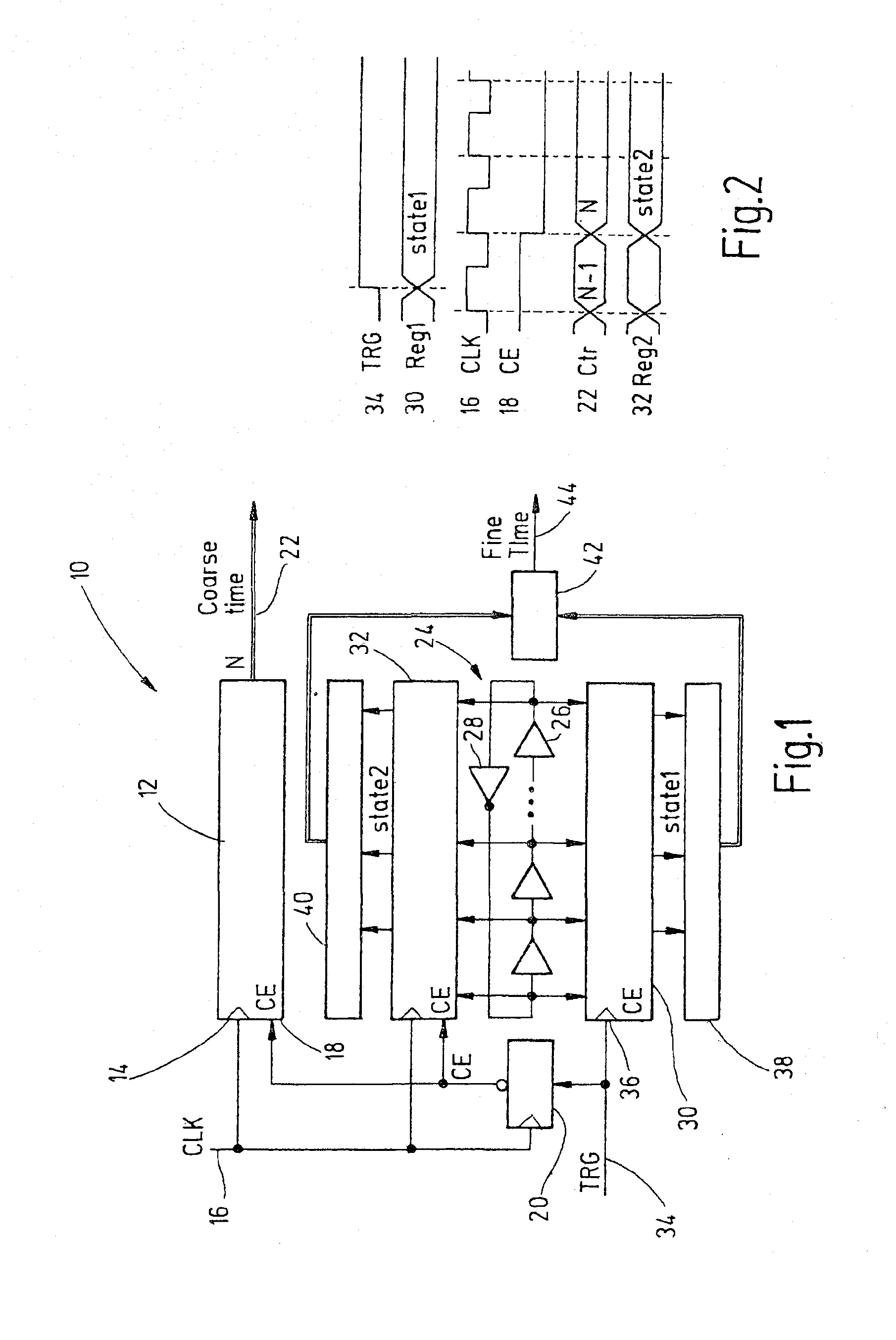
[0028]FIG. 1 shows a time-to-digital converter 10 comprising a ring oscillator 24. The time-to-digital conversion is a combination of coarse time conversion and fine time conversion. A coarse time is determined by a coarse time converter unit 12 having a first input 14 connected to a stable reference clock 16 and a second input 18 connected to the output of a D flip-flop 20. The second input 18 represents the COUNT ENABLE (CE) of the coarse counter 12. A count value C is output at the output 22 representing the coarse time to be converted.

[0029]A pulse is circulated in the ring oscillator 24 comprising a plurality of delay elements 26 and an odd number of inverters 28. The output of each delay element 26 and of said inverter 28 is connected to a first fine time register 30 as well as to a second fine time register 32. The state of the ring oscillator 24 is captured in the first fine time register 30 in response to a rising edge of a trigger signal 34 which is connected to the input ...


PUM


Abstract

A time-to-digital converter includes at least one chain of delay elements, a status of which represents a digital signal relating to a time interval to be converted. The converter includes a provider for providing trigger signals having statistically equally distributed variable positions relative to a pulse forwarded in the chain of delay elements, a capturer for capturing the status of the chain of delay elements in response to the calibration trigger signals, the status depending on delay times of the delay elements, a determiner for determining an actual contribution of at least some of the delay elements to an overall delay of the chain of delay elements on the basis of occurrences of pulse positions in response to the calibration trigger signals. The converter is configured to take into account the actual contribution of at least some of the delay elements when converting the time interval into said digital signal.

Description

BACKGROUND OF THE INVENTION[0001]The present invention relates to a time-to-digital converter and a method for time-to-digital conversion.SUMMARY[0002]According to an embodiment, a time-to-digital converter may have: at least one chain of delay elements, wherein a status of said chain of delay elements represents a digital signal relating to a time interval to be converted, a provider for providing calibration trigger signals having statistically equally distributed variable positions relative to a pulse forwarded in said chain of delay elements, capturer for capturing said status of said chain of delay elements in response to said calibration trigger signals, wherein said status depends on delay times of said delay elements, a determiner for determining an actual contribution of at least some of said delay elements to an overall delay of said chain of delay elements on the basis of occurrences of pulse positions in response to said calibration trigger signals, wherein the converter...

Claims


Application Information

Patent Timeline
Patent Type & Authority Applications(United States)
IPC IPC(8): H03M1/10H03M1/50
CPCG04F10/005H03M1/10H03M1/14H03M1/50
Inventor RIVOIR, JOCHEN
Owner ADVANTEST CORP
Why Eureka
Try Eureka