Resonant cap loaded high gain patch antenna

a patch antenna and high gain technology, applied in the field of radio communication antenna systems, can solve problems such as inability to be used

Active Publication Date: 2009-12-31
INTEL CORP
View PDF15 Cites 35 Cited by
  • Summary
  • Abstract
  • Description
  • Claims
  • Application Information

AI Technical Summary

Benefits of technology

[0011]In a preferred embodiment, the parasitic patch is adjacent to each edge of the resonant patch. The parasitic patches are preferably rectangular. In an embodiment, the resonant patch is generally coplanar with the plurality of parasitic patches. In a preferred embodiment, the dielectric sheet is configured to position the plurality of parasitic patches at an angle with respect to the vertical axis of the resonant patch. The plurality of parasitic patches are preferably positioned at an angle with respect to the vertical axis of the resonant patch in the range of approximately 20 degrees to approximately 35 degrees. The dielectric sheet is constructed from a material having a dielectric constant Er in a range of approximately 5.0 to approximately 10. The dielectric sheet is alternatively constructed from a material having a dielectric constant Er preferably in the range of approximately 4.6 and approximately 6. The plurality of parasitic patches preferably further comprises four outer parasitic patches positioned adjacent to the four outer edges of the inner parasitic patches. The length and width of the outer parasitic patches are preferably less than the length and width of the inner parasitic patches. and a second generally planar radiating element configured above and spaced apart from the first generally planar radiating element in a radiating direction. The antenna radiating structure may further comprise a second generally planar radiating element configured generally coplanar with the first generally planar radiating element and which has an aperture for radiative coupling thereto.

Problems solved by technology

Real world applications often call for an antenna radiating element with frequency bandwidth, pattern beamwidth and polarization requirements that may not be possible for conventional antenna radiating element designs to achieve due to overall mechanical constraints.

Method used


Image

  • Resonant cap loaded high gain patch antenna
  • Resonant cap loaded high gain patch antenna
  • Resonant cap loaded high gain patch antenna

Examples


Embodiment Construction

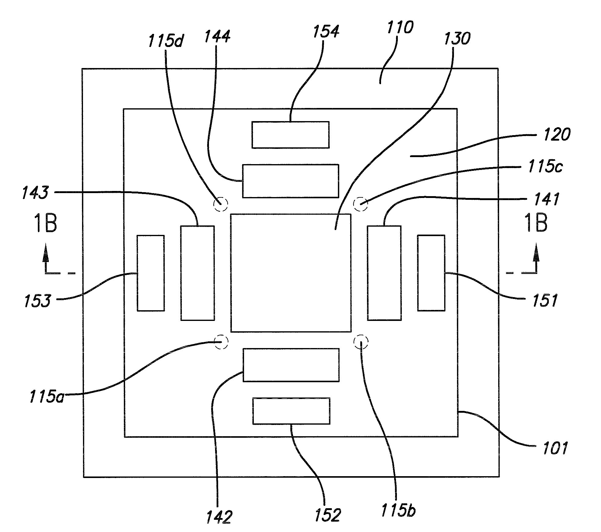
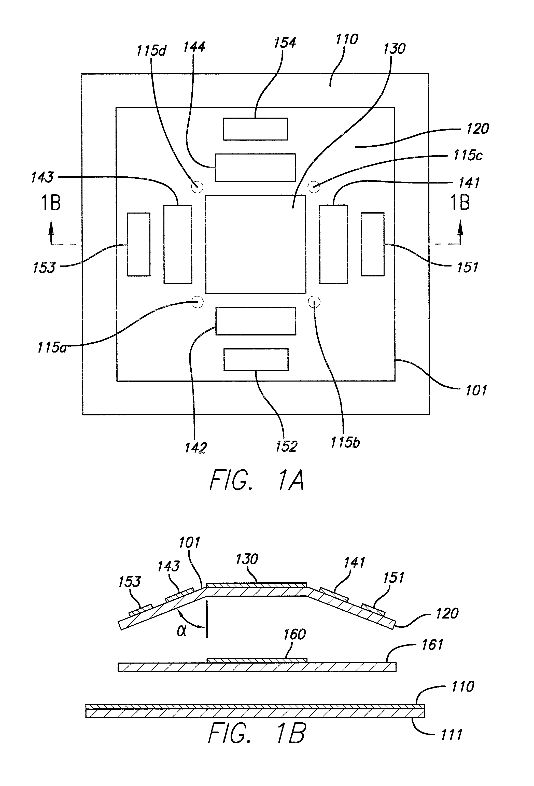
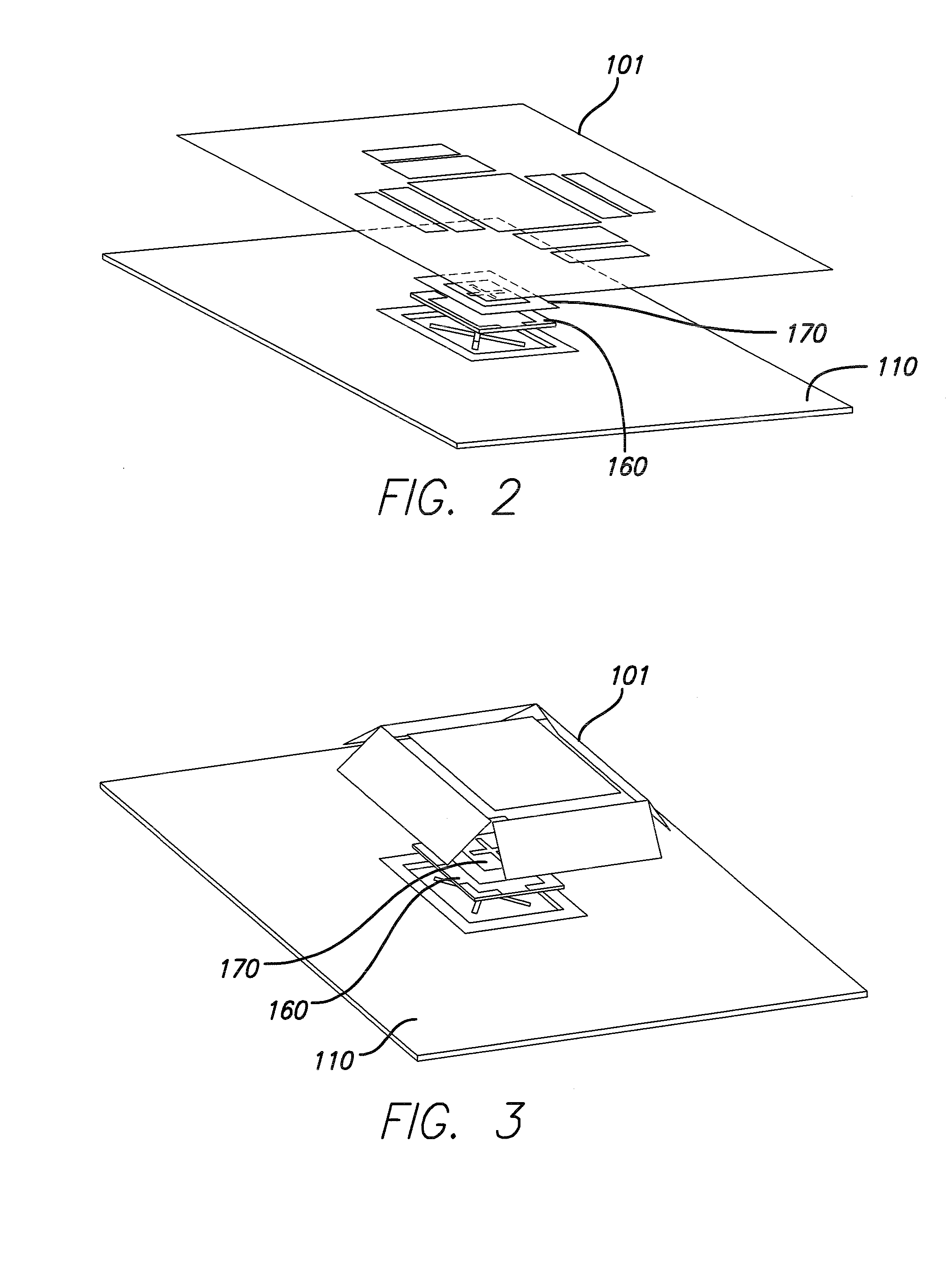
[0018]It is an object of the present invention to enhance the directivity of a standard radiating patch antenna through the use of a broadband resonant cap above a radiating patch and a ground plane. In an embodiment of the present invention, the resonant cap comprises a dielectric sheet, a resonant patch formed on the dielectric sheet, and a plurality of parasitic patches surrounding the resonant patch. The parasitic patches may be coplanar or tilted at an angle with respect to the plane of the resonant patch. The gaps and lengths of the parasitic patches are preferably selected to allow appropriate amplitude weighting for sidelobe suppression.

[0019]In an embodiment of the invention, a resonant cap is positioned over a generally planar radiating element and a ground plane. The generally planar radiating element is disposed on a dielectric substrate, and the metallic ground plane is disposed on a ground plane dielectric substrate. The resonant cap, the generally planar radiating ele...


PUM


Abstract

An antenna architecture containing a broadband resonant cap positioned over a radiating patch is disclosed. The resonant cap consists of a rectangular resonant patch at the center with parasitic patches in close proximity of the four edges of the resonant patch. The parasitic patches may be coplanar with the resonant patch or may be mounted at an angle with respect to the vertical axis of the resonant patch. The resonant cap reduces the HPBW of the emitted radiation and improves emission directivity.

Description

RELATED APPLICATION INFORMATION[0001]The present application claims priority under 35 USC section 119(e) to U.S. provisional patent application Ser. No. 61 / 133,147 filed Jun. 25, 2008, the disclosure of which is incorporated herein by reference in its entirety.BACKGROUND OF THE INVENTION[0002]1. Field of the Invention[0003]The present invention relates to radio communication antenna systems for wireless networks. More particularly, the invention is directed to high-gain radiating patch antennas and antenna arrays.[0004]2. Description of the Prior Art and Related Background Information[0005]Modern wireless antenna systems generally include a plurality of radiating elements that may be arranged over a ground plane defining a radiated (and received) signal beamwidth and azimuth angle. Antenna beamwidth has been conventionally defined by Half Power Beam Width (“HPBW”) of the azimuth or elevation beam relative to a bore sight of such antenna element.[0006]Real world applications often ca...

Claims


Application Information

Patent Timeline
Patent Type & Authority Applications(United States)
IPC IPC(8): H01Q1/38H01Q1/48
CPCH01Q1/42H01Q19/005H01Q9/0414
Inventor FOO, SENGLEE
Owner INTEL CORP
Why Eureka
Try Eureka