Image Processor, Image Processing Method, And Vehicle Including Image Processor

a technology of image processing and image processor, applied in the field of image processing of camera images, can solve the problems of difficult measurement or estimation of accurate transformation parameters, inability to draw far away images, and inability to adjust the high-angle view image, etc., to achieve less susceptible to camera installation errors.

Inactive Publication Date: 2009-12-31
SANYO ELECTRIC CO LTD
View PDF3 Cites 36 Cited by
  • Summary
  • Abstract
  • Description
  • Claims
  • Application Information

AI Technical Summary

Benefits of technology

[0012]This invention was made in view of the above problems, and one object of this invention, therefore, is to provide an image processor and an image processing method that can achieve image processing that is less susceptible to camera installation errors while assuring an image display that encompasses a wide region, and to provide a vehicle utilizing such an image processor.

Problems solved by technology

While the mounting angle of the camera and the installation height of the camera are often designed beforehand, errors may occur between such designed values and the actual values when a camera is installed on a vehicle, and therefore, it is often difficult to measure or estimate accurate transformation parameters.
Thus, the coordinate conversion based on the perspective projection transformation is susceptible to installation errors of the camera.
However, the high-angle view image is not suitable to draw far away images from the vehicle by its nature.
That is, in a system that simply displays a high-angle view, there is a problem that it is difficult to display images captured by the camera that are of objects distant from the vehicle.
However, the perspective projection transformation is necessary in order to achieve the technique described in Japanese Patent Application Laid-Open No. 2006-287892, which makes it susceptible to camera installation errors.
Although the planar projective transformation can absorb camera installation errors, the technique described in Japanese Patent Application Laid-Open No. 2006-287892 cannot be achieved by using the planar projective transformation.

Method used


Image

  • Image Processor, Image Processing Method, And Vehicle Including Image Processor
  • Image Processor, Image Processing Method, And Vehicle Including Image Processor
  • Image Processor, Image Processing Method, And Vehicle Including Image Processor

Examples


Embodiment Construction

[0035]Preferred embodiments of the invention will be described below with reference to the accompanying drawings. The same reference numbers are assigned to the same parts in each of the drawings being referred to, and overlapping explanations for the same parts are omitted in principle.

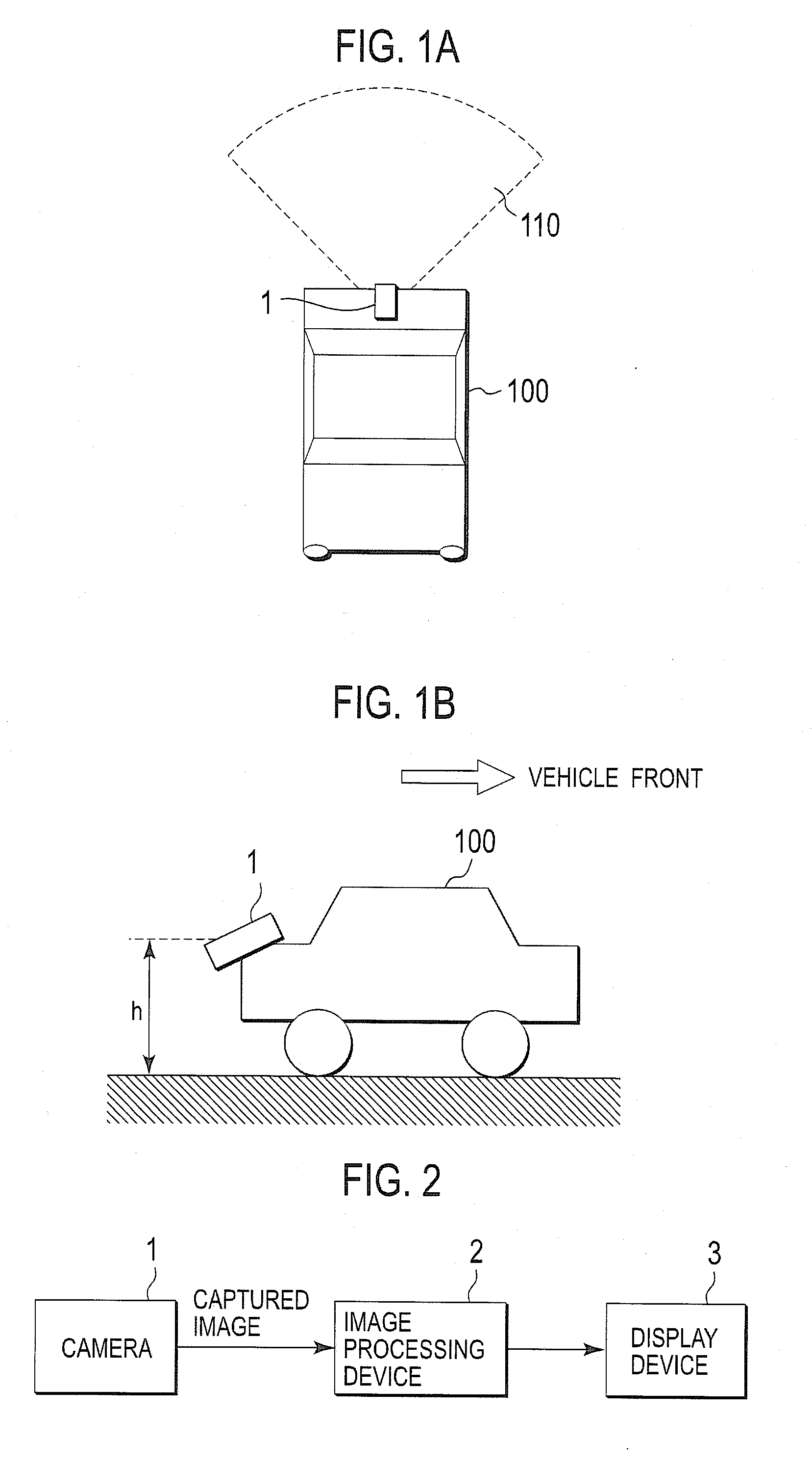
[0036]FIG. 1A is a top plan view of a vehicle 100, such as a car. FIG. 1B is a side view of the vehicle 100. The vehicle 100 is positioned on the ground. A camera 1 is installed at the rear of the vehicle 100 for supporting visual safety confirmation of the vehicle when moving backward. The camera 1 is installed such that it has a field of view of the area rearward of the vehicle 100. The fan-shaped area 110 of the dotted-line shows an image-capturing region of the camera 1. The camera 1 is installed to be directed downward such that the ground near the rear of the vehicle 100 is included in the field of view of the camera 1. While a regular passenger car is illustrated for the vehicle 100 by an exam...


PUM


Abstract

A visibility support system is provided which displays a wide field of view while absorbing camera installation errors. The visibility support system obtains a first conversion matrix H1 for projecting a captured image onto the ground, while a second conversion matrix H2 for projecting the captured image on a plane different from the ground (e.g. no-conversion unit matrix) is set. An extended high-angle view image is divided into a first region corresponding to the vehicle periphery and a second region corresponding to farther away from the vehicle, and a high-angle view image based on H1 is displayed in the first region, whereas an image based on a weight-added conversion matrix in which H1 and H2 are weight-added is displayed in the second region. Weight for the weight-addition is varied according to a distance from the border of the first and second regions to seamlessly join the images in both regions.

Description

CROSS REFERENCE TO RELATED APPLICATIONS[0001]This application claims priority under 35 USC 119 from prior Japanese Patent Application No. P2007-113079 filed on Apr. 23, 2007, the entire contents of which are incorporated herein by reference.BACKGROUND OF THE INVENTION[0002]1. Field of the Invention[0003]This invention relates generally to image processing of camera images, and more particularly to vehicle peripheral visibility support technology that generates and displays an image similar to a high-angle view image by processing a captured image of an on-vehicle camera. This invention also relates to a vehicle utilizing such an image processor.[0004]2. Description of Related Art[0005]With the increased safety awareness of recent years, it is becoming more common to mount a camera on a vehicle such as a car. Also, instead of simply displaying the captured image, research has been made to provide more user-friendly images by utilizing image processing technology. One such technology ...

Claims


Application Information

Patent Timeline
Patent Type & Authority Applications(United States)
IPC IPC(8): H04N7/18H04N5/228
CPCB60R1/00G06T3/0012B60R2300/607
Inventor ISHII, YOHEI
Owner SANYO ELECTRIC CO LTD
Why Eureka
Try Eureka