Illumination device and liquid crystal display apparatus

a technology of liquid crystal display and illumination device, which is applied in the direction of lighting device details, lighting and heating apparatus, instruments, etc., can solve the problems of joint fragmentation, stress applied, and joint fragmentation, and achieve the effect of reducing the number of defective units to be wasted due to failed rework during the manufacturing process and low cos

Inactive Publication Date: 2009-12-31
EPSON IMAGING DEVICES CORP +1
View PDF6 Cites 42 Cited by
  • Summary
  • Abstract
  • Description
  • Claims
  • Application Information

AI Technical Summary

Benefits of technology

[0021]According to the configuration as described above, the number of defective units to be wasted due to failed rework duri...

Problems solved by technology

However, since the LEDs mounted on the FPC have no flexibility, if the FPC is deformed, there is a problem such that an excessive stress is applied to joint portions between terminals of the LEDs and the FPC by soldering...

Method used


Image

  • Illumination device and liquid crystal display apparatus
  • Illumination device and liquid crystal display apparatus
  • Illumination device and liquid crystal display apparatus

Examples


Embodiment Construction

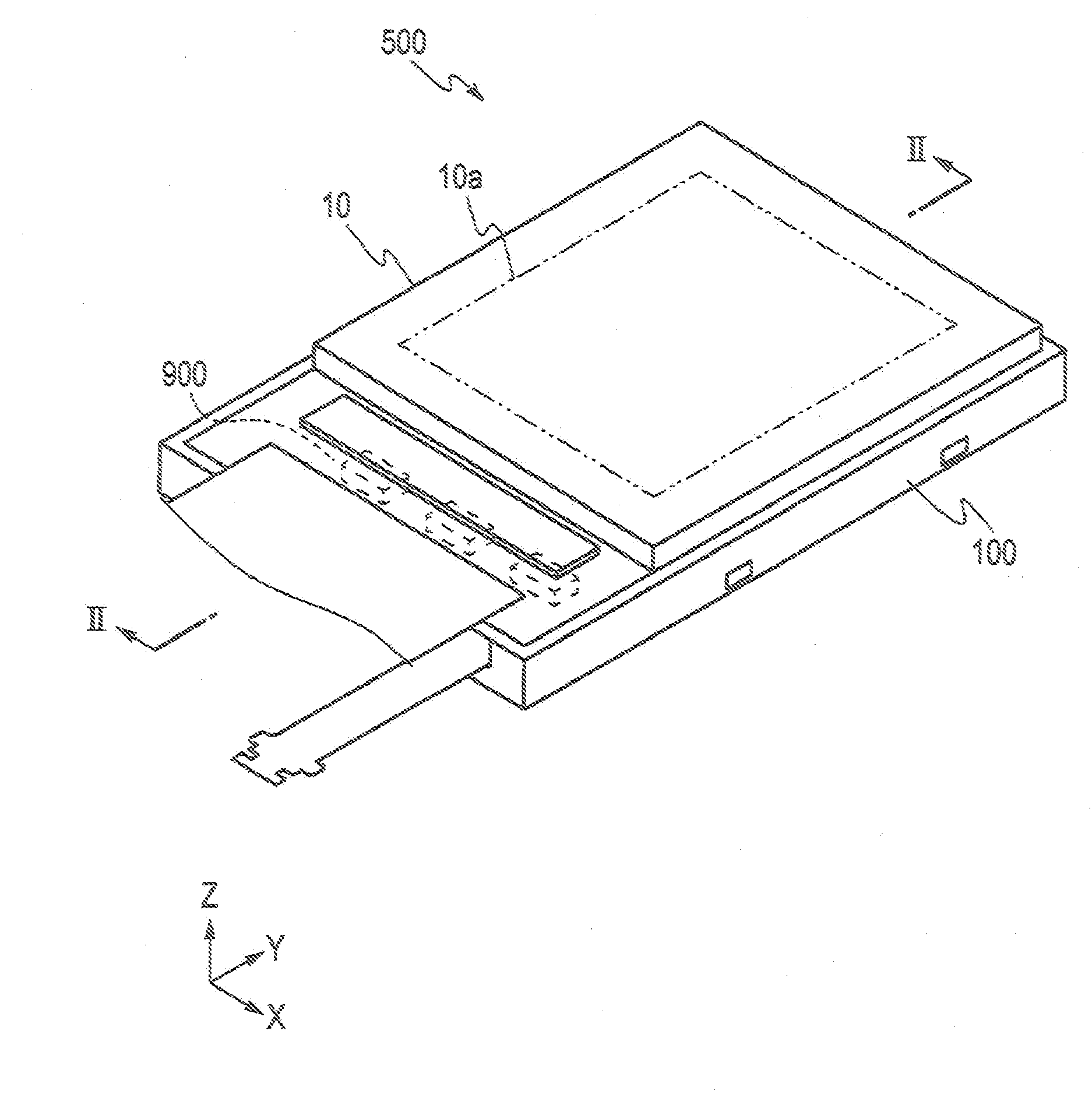
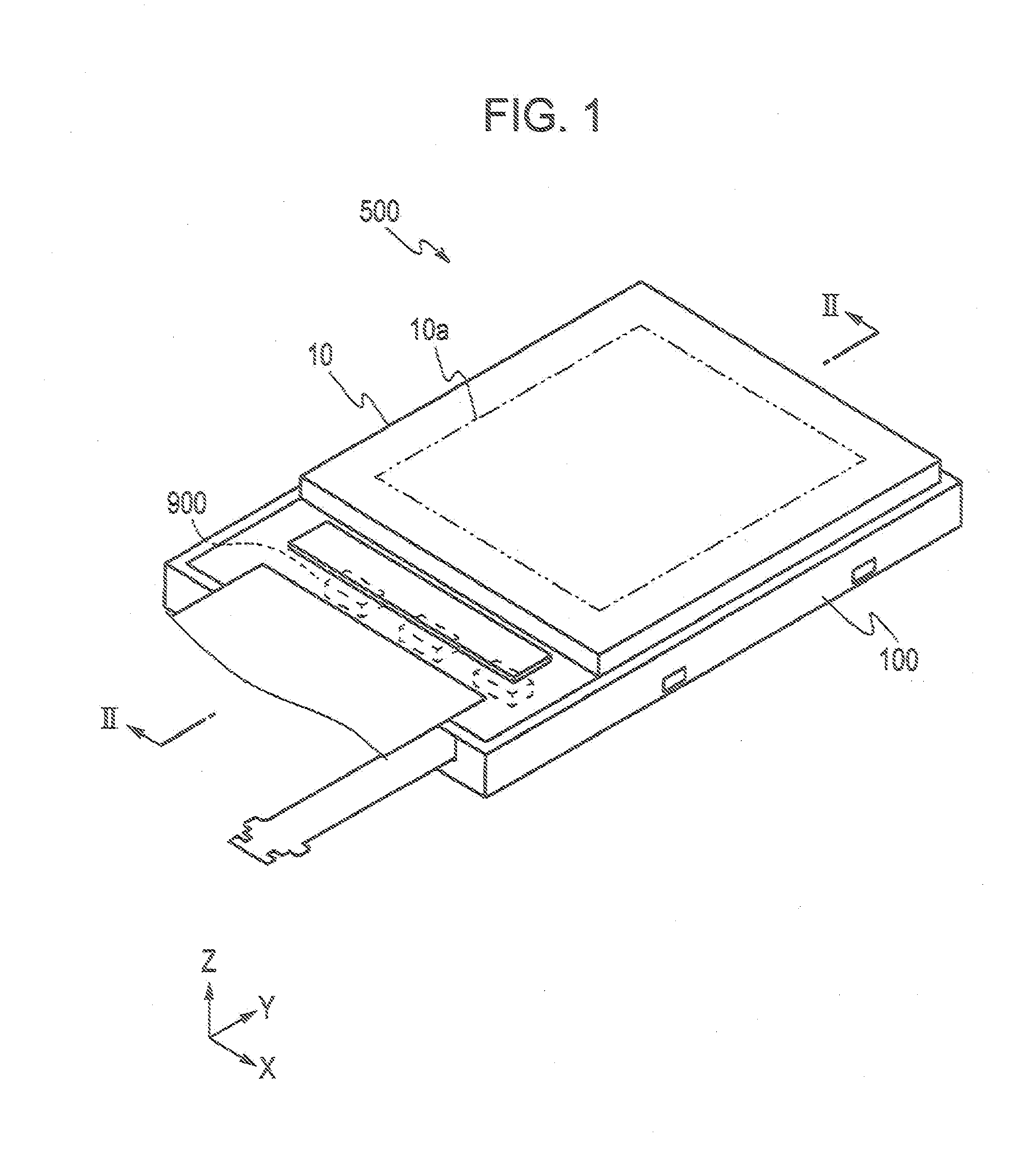
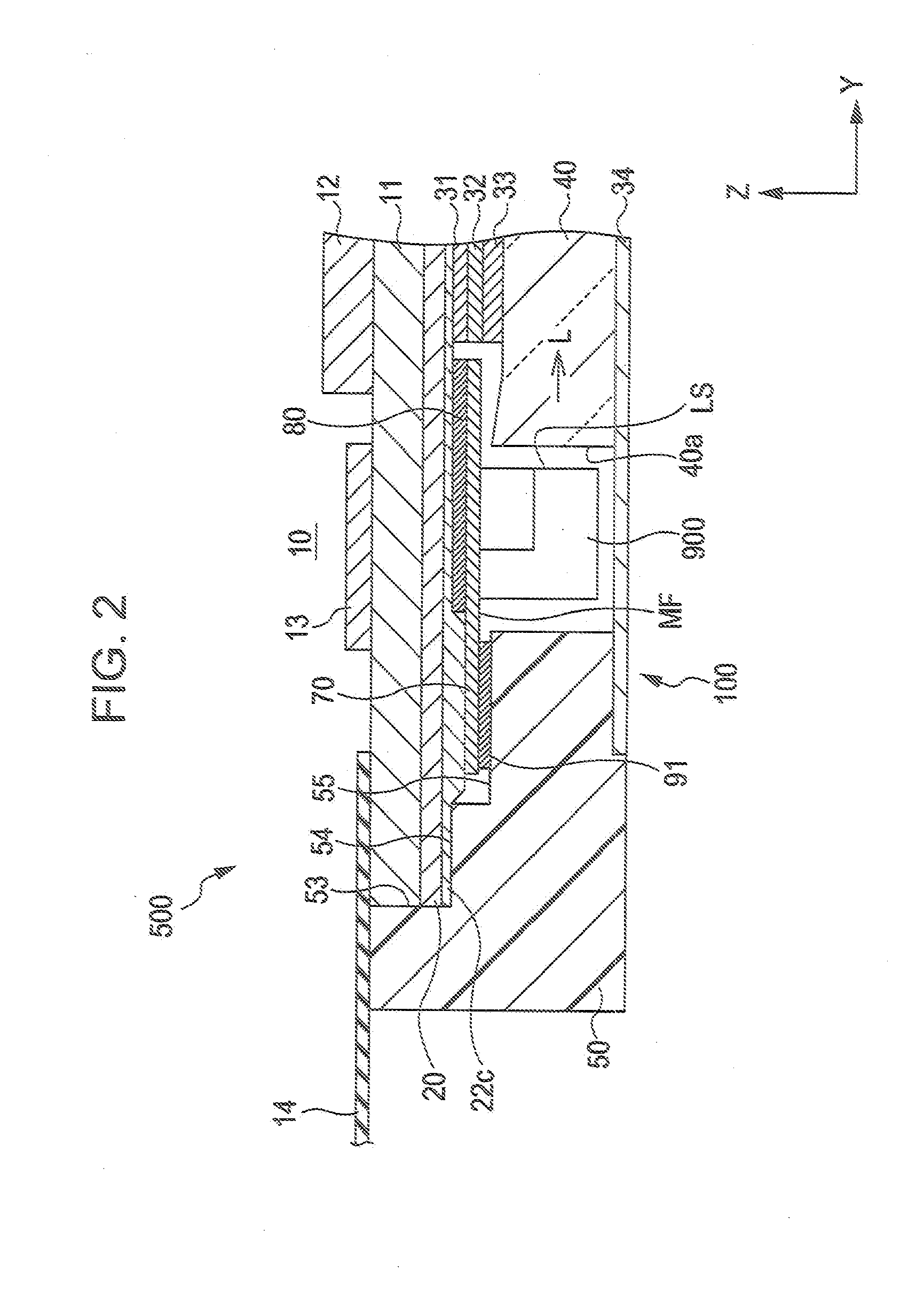
[0030]Referring now to the drawings, an example in which an aspect of the invention is applied as a liquid crystal display apparatus and a backlight unit thereof will be described. In the drawings used for description given below, the contraction scales of respective members are changed as needed in order to ensure the visibility of the respective member in the drawing. FIG. 1 is a perspective view of a liquid crystal display apparatus 500. FIG. 2 is a cross-sectional view taken along the line II-II in FIG. 1. FIG. 3 is an exploded perspective view of the liquid crystal display apparatus 500.

[0031]The liquid crystal display apparatus 500 in this embodiment is a so-called transmissive liquid crystal display apparatus including a transmissive liquid crystal panel 10, and a backlight unit 100 as an illumination device having light emitting diodes (hereinafter referred to as “LEDs”) as light source members.

[0032]The liquid crystal display apparatus 500 in this embodiment includes the li...


PUM


Abstract

An illumination device comprising: a wired board having flexibility and including a light source member mounted on one of principal planes; a light-shielding member disposed so as to cover at least part of the other principal plane of the wired board on the opposite side from the one principal plane and having at least partly a light-shielding property; a fixing member having first and second sticking surfaces to which the wired board and the light-shielding member are stuck respectively, a first adhesive layer being interposed between the one principal plane of the wired board and the first sticking surface of the fixing member, having an adhesive property with respect to both of the one principal plane of the wired board and the first sticking surface, and having a first adhesive force with respect to the one principal plane, and a second adhesive layer being disposed on a surface opposing the fixing member of the light-shielding member, and having a portion having an adhesive property with respect to both of the light-shielding member and the second sticking surface and a portion having an adhesive property for both of the light-shielding member and the other principal plane of the wired board, wherein the second adhesive layer includes a non-adhesive portion having no adhesive property with respect to the other principal plane or a low-bond strength adhesive portion having a second adhesive force lower than the first adhesive force at least in a portion having an adhesive force for both the light-shielding member and the other principal plane of the wired board.

Description

[0001]The entire disclosure of Japanese Patent Application No. 2006-101625, filed Apr. 3, 2006 is expressly incorporated by reference herein.BACKGROUND[0002]1. Technical Field[0003]The present invention relates to an illumination device and a liquid crystal display apparatus, and more specifically, to an illumination device and a liquid crystal display apparatus including a flexible wired board having a light source member mounted one of principal planes thereof.[0004]2. Related Art[0005]In general, an illumination device which outputs light emitted from a light source to a predetermined direction by guiding the light by a light guide member formed of translucent material such as acrylic is known as an illumination device which outputs light emitted from a light emitting diode (hereinafter referred to as “LED), which corresponds to the light source, to a predetermined direction.[0006]Such illumination device is used, for example, as a backlight unit of a side light type in the liqui...

Claims


Application Information

Patent Timeline
IPC IPC(8): G02F1/1335F21V7/04
CPCG02F1/1336G02F1/133615
Inventor HASHINO, NARUO
Owner EPSON IMAGING DEVICES CORP
Why Eureka
Try Eureka