

Lens array, LED print head, exposure device, image forming apparatus, and reading apparatus
a technology of led print head and exposure device, which is applied in the field of led print head, exposure device, image forming apparatus, reading apparatus, can solve the problems of difficult to form the opening portions of the light blocking plate, and achieve the effect of increasing the lifetime and productivity of the metal mold and facilitating the production of the light blocking member
- Summary
- Abstract
- Description
- Claims
- Application Information
AI Technical Summary
Benefits of technology
Problems solved by technology
Method used
Image

Examples
first embodiment
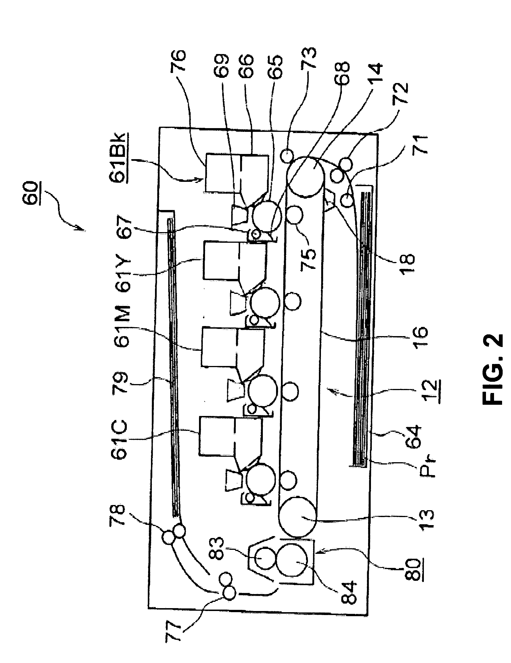
[0049]A first embodiment of the present invention will be explained. First, a printer 60 as an image forming apparatus will be explained. FIG. 2 is a schematic sectional view showing a configuration of the printer 60 according to the first embodiment of the present invention.
[0050]As shown in FIG. 2, the printer 60 includes image forming units 61K, 61Y, 61M, and 61C for forming toner images as developer images in colors such as black, yellow, magenta, and cyan according to image data; and a transfer unit 12 disposed to face the image forming units 61K, 61Y, 61M, and 61C for forming transfer areas of colors with respect to the image forming units 61K, 61Y, 61M, and 61C, so that the toner images in colors are transferred to a sheet Pr as a medium.
[0051]In the embodiment, the printer 60 further includes a sheet supply cassette 64 as a medium storage unit; a sheet supply roller 71 as a medium supply roller for picking up the sheet Pr from the sheet supply cassette 64 one by one and supp...
second embodiment
[0107]A second embodiment of the present invention will be explained next. Components in the second embodiment similar to those in the first embodiment are designated with the same reference numerals, and explanations thereof are omitted.
[0108]FIG. 13 is a schematic plan view showing an aperture plate 40 according to the second embodiment of the present invention. FIG. 14 is a schematic enlarged plan view showing the aperture plate 40 according to the second embodiment of the present invention. FIG. 15 is a schematic enlarged sectional view showing the aperture plate 40 according to the second embodiment of the present invention. FIG. 16 is a schematic sectional view showing the aperture plate 40 taken along a line 16-16 in FIG. 14 according to the second embodiment of the present invention.
[0109]As shown in FIGS. 14 to 16, the aperture plate 40 as the light blocking member includes a light blocking portion 40a and light transmission portions 40b. As shown in FIG. 13, the light tran...
third embodiment
[0119]A third embodiment of the present invention will be explained next. Components in the third embodiment similar to those in the first and second embodiments are designated with the same reference numerals, and explanations thereof are omitted.
[0120]FIG. 17 is a schematic plan view showing an aperture plate 45 according to the third embodiment of the present invention. FIG. 18 is a schematic enlarged plan view showing the aperture plate 45 according to the third embodiment of the present invention. FIG. 19 is a schematic enlarged sectional view showing the aperture plate 45 according to the third embodiment of the present invention. FIG. 20 is a schematic sectional view showing the aperture plate 45 taken along a line 20-20 in FIG. 18 according to the third embodiment of the present invention. FIG. 21 is a schematic plan view showing the lens array 30 according to the third embodiment of the present invention. FIG. 22 is a schematic sectional view showing the lens array 30 accor...
PUM
 Abstract
Description
Claims
Application Information