Side-emitting LED display

a technology of led display and side-emitting light, which is applied in the field of display media with backlit display, can solve the problems of unpredictable color variations across backlit displays, white led's are considerably more expensive, and the use of white led's in backlit display applications has in practice been limited to small display areas

Inactive Publication Date: 2009-12-31
VISTEON GLOBAL TECH INC
View PDF8 Cites 21 Cited by
  • Summary
  • Abstract
  • Description
  • Claims
  • Application Information

AI Technical Summary

Benefits of technology

[0013]Concordant and consistent with the present invention, a backlit display that maintains a suitable illumination homogeneity while minimizing the number of required light sources, has surprisingly been discovered.
[0017]The invention offers a number of advantages. The direction of the emitted optical radiation towards the primary diffusing reflector prevents direct un-diffused illumination emitted by the LED from reaching the graphical information display areas, and this helps to ensure evenness of illumination.
[0018]Other advantages stem from the lateral direction of the emitted optical radiation from the primary diffuser. The optical radiation from an LED will naturally have a certain spread, for example about a beam axis, which is preferably oriented to be normal to the primary diffuser surface. Optical radiation from the LED traveling in a direction laterally away from the graphical information display area will then be essentially entirely incident on the primary diffuser reflector, which preferably bounds along one side of the graphical information display area. The diffuse reflector, being oriented transverse, and most preferably perpendicular, to the display panel will therefore also diffusely reflect the optical radiation, primarily in a direction that is oppositely lateral to the direction of the optical radiation originally incident on the primary diffusive reflector. The predominantly lateral direction of both the incident optical radiation and diffuse reflection helps to spread the optical radiation over the display panel and graphical information areas while minimizing the size of the display unit in the direction transverse to the display panel. As a result, the thickness and complexity of the display unit can be minimized and the number of LEDs reduced whilst providing an even back-lighting for the graphical information display area. To help further minimize the required thickness of the display unit, the primary diffusing reflector may be located immediately behind the graphical information display area.

Problems solved by technology

White LED's are, however, considerably more expensive than incandescent bulbs, and so it is in almost all causes uneconomic simply to replace each incandescent light with an LED.
This can lead to unpredictable color variations across a backlit display.
Therefore, the use of white LED's in backlit display applications has in practice been limited to small area displays both for reasons of cost and for color uniformity.
The balancing consists on darkening the bright spots to the level of the low brightness spots but this method suffers from a noticeable colour shift that occurs when a polychromatic source is employed such as white light which is due to the difference in the spectrum of absorption of light induced by the additional painting or darkening layers.
Such techniques efficiently use the available optical power of an LED but require additional design, assembly and tooling costs.
Furthermore, light guides are not scalable as these need to be precisely designed for each application and depend critically on the size of the area to be illuminated.
The drawback of this method is that part of the light emitted by the LED is transmitted without being diffused or reflected by the diffusing reflector, and therefore produces uneven illumination and color shift.

Method used


Image

  • Side-emitting LED display
  • Side-emitting LED display

Examples


Embodiment Construction

[0026]The following detailed description and appended drawings describe and illustrate various embodiments of the invention. The description and drawings serve to enable one skilled in the art to make and use the invention, and are not intended to limit the scope of the invention in any manner.

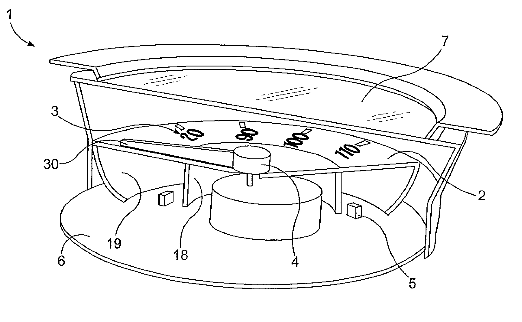
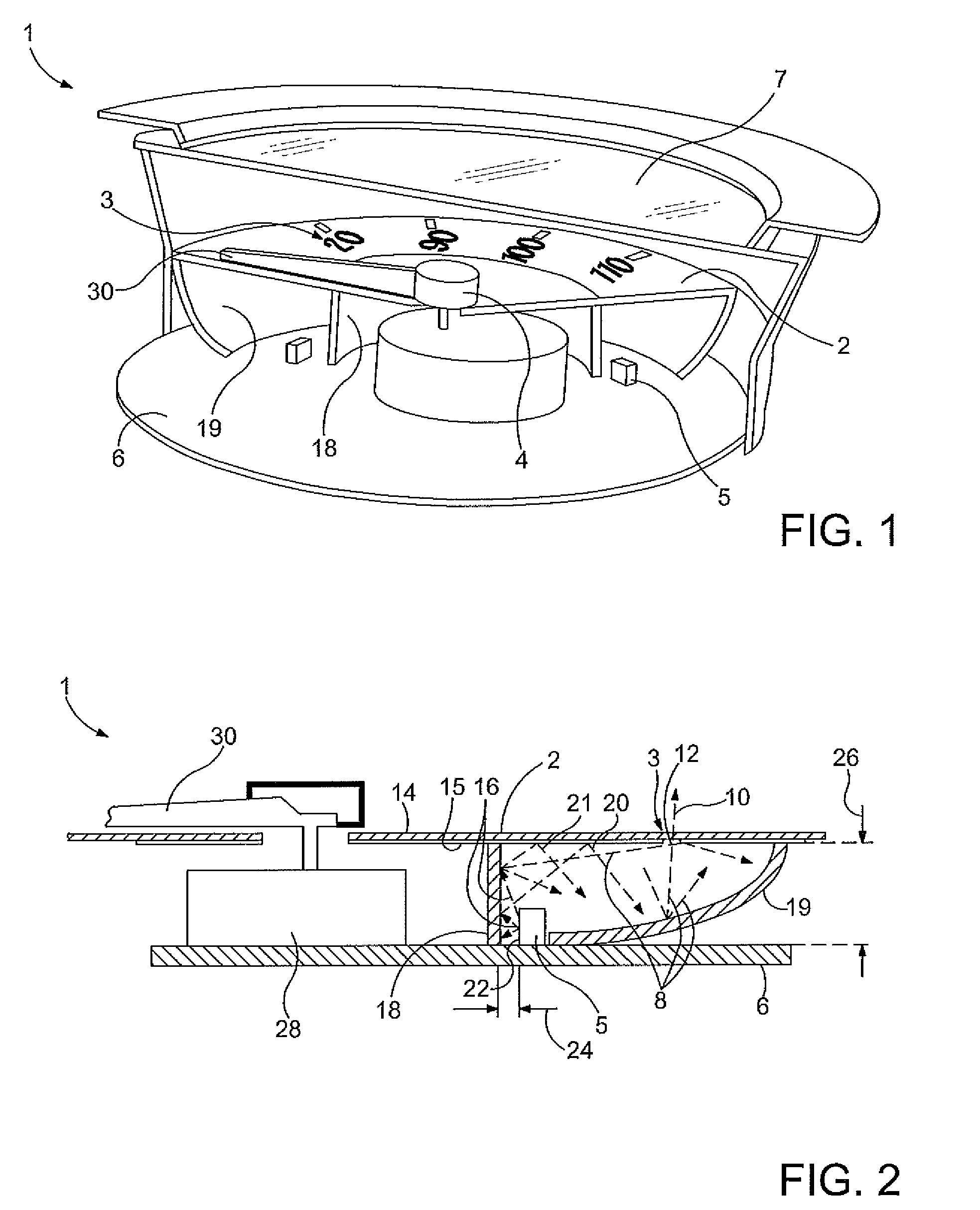
[0027]FIGS. 1 and 2 show a display unit 1 including a display panel 2 having a graphical information display area 3 for displaying graphical information to a user of the unit. An optical system is used to provide diffuse back-light illumination 8 to the display area 3. As shown, a portion 10 of the back-light illumination 8 passes through a plurality of areas 12 of relatively high transmittance in the display panel 2 to present graphical information to a user of the display unit 1.

[0028]The display panel 2 has a translucent upper layer 14 a lower side of which is covered by one of more layers of an opaque paint 15. The paint 15 is absent in the areas 12 having relatively higher transmittance. ...


PUM


Abstract

A display unit is disclosed. The display unit includes a display panel having a graphical information display area for displaying graphical information to a user of the unit, a diffusing means including a primary diffusing reflector and a secondary diffusing reflector disposed adjacent the display panel, wherein the primary diffusing reflector extends transversely away from the display panel, and a source of optical radiation spaced from the diffusing means, the source of optical radiation having an emitting side that faces in a lateral direction with respect to the extent of the display panel and towards the primary diffusing reflector and so that optical radiation from the source of optical radiation is directed toward the primary diffusing reflector.

Description

CROSS-REFERENCE TO RELATED APPLICATION[0001]This application claims the benefit of United Kingdom Patent Application No. 0811866.3 filed on Jun. 27, 2008, hereby incorporated herein by reference in its entirety.FIELD OF THE INVENTION[0002]The present invention related to the field of the illuminating of displays, and in particular to displays having a back-lit display medium.BACKGROUND OF THE INVENTION[0003]Displays are often provided with backlighting, used to provide illumination through clear or translucent portions of components forming the display. Examples include liquid crystal displays (LCD's), or indication displays having an appliqué with transparent or translucent portions through which the backlit illumination passes.[0004]Examples in the field of automotive displays include LCD displays for displaying alphanumeric of graphical information, and speedometer or engine speed (rpm) displays having translucent numeric indications.[0005]Traditionally, such displays have been i...

Claims


Application Information

Patent Timeline
Patent Type & Authority Applications(United States)
IPC IPC(8): F21V13/08F21K99/00
CPCB60Q3/044G12B11/02G01D13/20G01D11/28B60Q3/14
Inventor MEZOUARI, SAMIR
Owner VISTEON GLOBAL TECH INC
Why Eureka
Try Eureka