
Method of Limiting the Non-Linear Phase Noise of a Phase-Modulated Optical Signal of Constant Amplitude, and an Associated Device

a phase-modulated optical signal and phase-modulated technology, applied in the field of optical fiber telecommunications, can solve the problems of not enabling unable to compensate cd and pmd, and unable to achieve effective digital signal processing, etc., to achieve the effect of improving the situation

Inactive Publication Date: 2009-12-31
FRANCE TELECOM SA
View PDF2 Cites 0 Cited by
  • Summary
  • Abstract
  • Description
  • Claims
  • Application Information

AI Technical Summary

Benefits of technology

[0017]An illustrative, non-limiting aspect of the disclosure seeks to improve the situation with the help of a non-linear phase noise limiter device for limiting the non-linear phase noise that affects a phase-modulated input optical signal of constant mean amplitude conveyed over a transmission line.

Problems solved by technology

It therefore does not enable effective digital signal processing to be performed, and it does not enable CD and PMD to be compensated.
A major drawback of the M-PSK type phase modulation format is that it is sensitive to distortion introduced by the non-linear effects that are excited in the transmission optical fiber, and in particular the Kerr effect.
Unfortunately, with M-PSK type modulation, it is the phase of the optical signal that carries the useful binary information.
As a result, such non-linear phase noise progressively pollutes the useful information carried by the optical signal.
A first drawback of such a device is that it requires amplitude fluctuations to be suppressed on two intensity levels “1” and “0”, and that is difficult to achieve since such two-level suppression requires the saturable absorber to present a transfer function that is close to ideal in the form of a staircase.
Existing components turn out to very effective at cleaning “0s”, but their performance is not so good for “1” levels.
A second drawback of such a device lies in its complexity and its cost, due to the presence of a phase-to-amplitude converter and of an amplitude-to-phase converter.

Method used


Image

  • Method of Limiting the Non-Linear Phase Noise of a Phase-Modulated Optical Signal of Constant Amplitude, and an Associated Device
  • Method of Limiting the Non-Linear Phase Noise of a Phase-Modulated Optical Signal of Constant Amplitude, and an Associated Device
  • Method of Limiting the Non-Linear Phase Noise of a Phase-Modulated Optical Signal of Constant Amplitude, and an Associated Device

Examples


Embodiment Construction

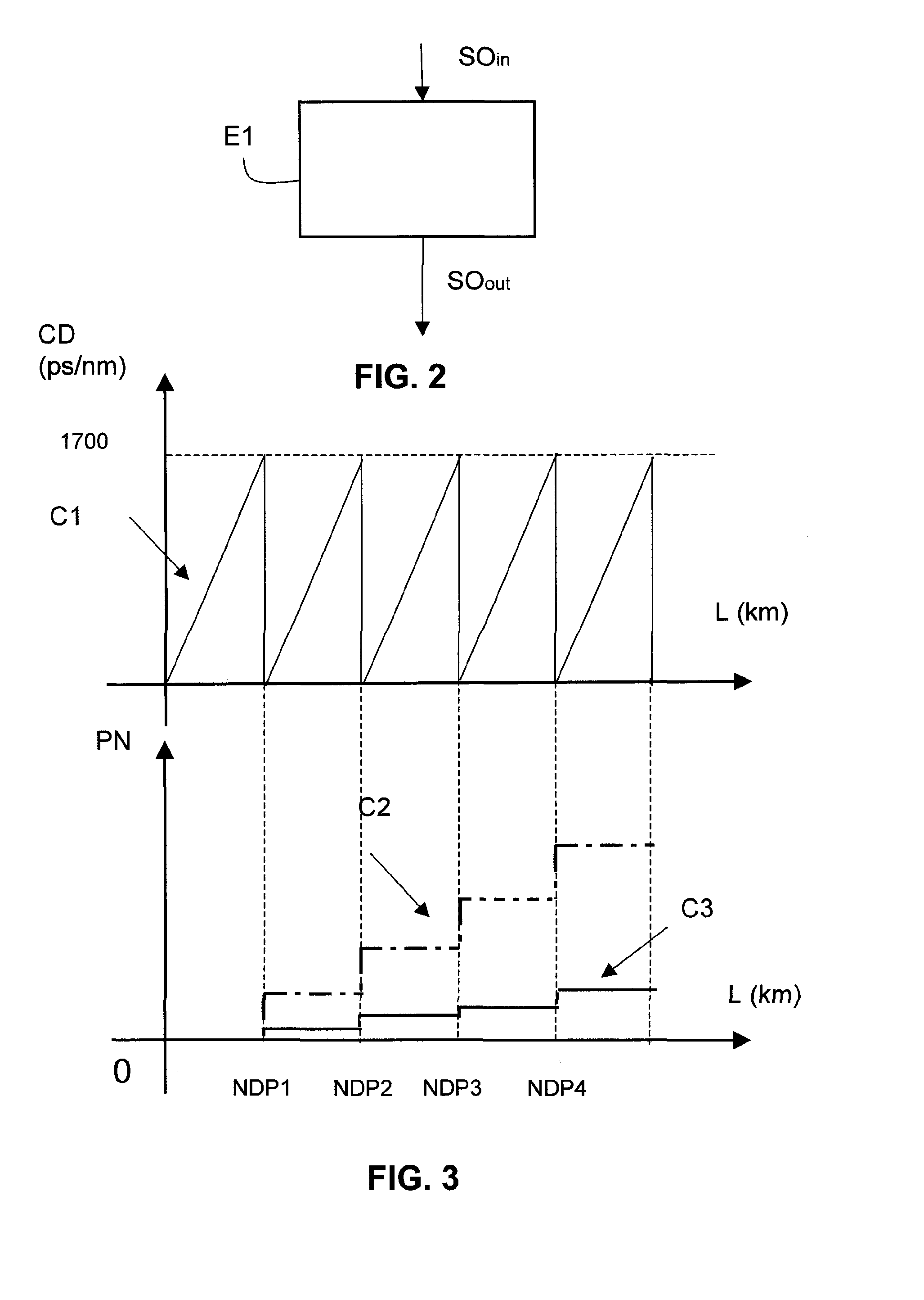
[0045]The general principle of an exemplary aspect of the disclosure relies on eliminating amplitude fluctuations around a mean amplitude value of a phase-modulated optical signal that is being conveyed by an optical fiber transmission line. Such suppression of fluctuations makes it possible to maintain the power of the optical signal constant and thus to limit the generation of non-linear phase noise during propagation by interaction of the phase-modulated signal with the optical fiber and by excitation of non-linear effects.

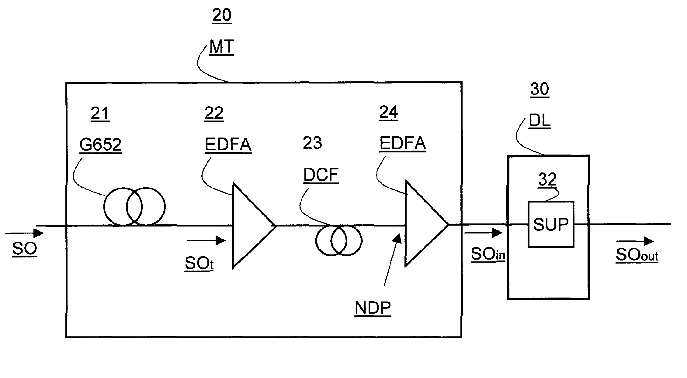
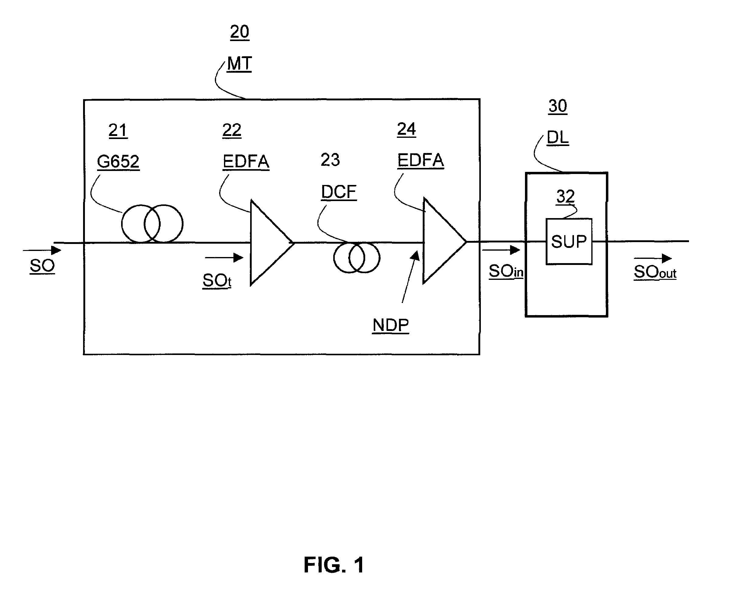
[0046]With reference to FIG. 1, there can be seen a diagram of a phase noise limiter device DL 30 according to an exemplary aspect of the disclosure, in its environment. In the example of FIG. 1, there is shown a portion of a transmission line comprising a transmission module MT 20 and the device DL 30. Such a span may be placed anywhere along the transmission line between the transmitter and the receiver.

[0047]In this example, the optical signal is carried on ...


PUM


Abstract

A non-linear phase noise limiter device limits the non-linear phase noise that affects a phase-modulated input optical signal of constant mean amplitude conveyed over a transmission line. The device is placed at a zero dispersion point of the transmission line, and it is suitable for suppressing amplitude fluctuations about a mean value in said optical signal.

Description

CROSS-REFERENCE TO RELATED APPLICATIONS[0001]None.STATEMENT REGARDING FEDERALLY SPONSORED RESEARCH OR DEVELOPMENT[0002]None.THE NAMES OF PARTIES TO A JOINT RESEARCH AGREEMENT[0003]None.FIELD OF THE DISCLOSURE[0004]The field of the disclosure is that of telecommunications, and more particularly that of optical fiber telecommunications.[0005]The present disclosure relates to a non-linear phase noise limiter device for limiting the non-linear phase noise that affects a phase-modulated optical signal at constant amplitude conveyed by an optical fiber transmission line.[0006]The disclosure applies in particular to a phase-modulated optical signal of constant amplitude or power, in particular a signal modulated with a format of the M-ary phase shift keying (M-PSK) type, e.g. of the binary, quaternary, or 2N type (B-PSK, Q-PSK, 2N-PSK).BACKGROUND OF THE DISCLOSURE[0007]This type of format is presently in ever-increasing use for optical fiber transmission over long distances. An advantage o...

Claims


Application Information

Patent Timeline
IPC IPC(8): H04B10/00H04B10/2513H04B10/2543
CPCH04B10/2543H04B10/2513
Inventor PINCEMIN, ERWANGOSSET, CHRISTOPHE
Owner FRANCE TELECOM SA
Learn More