Two-Train Catalytic Gasification Systems
a gasification system and catalytic technology, applied in the direction of gasifier mechanical details, combustible gas purification/modification, combustible gas production, etc., can solve the problems of increased production cost, loss of efficiency, over- or under-burden, etc., and achieve the effect of reducing moisture conten
- Summary
- Abstract
- Description
- Claims
- Application Information
AI Technical Summary
Benefits of technology
Problems solved by technology
Method used
Image
Examples
example 1
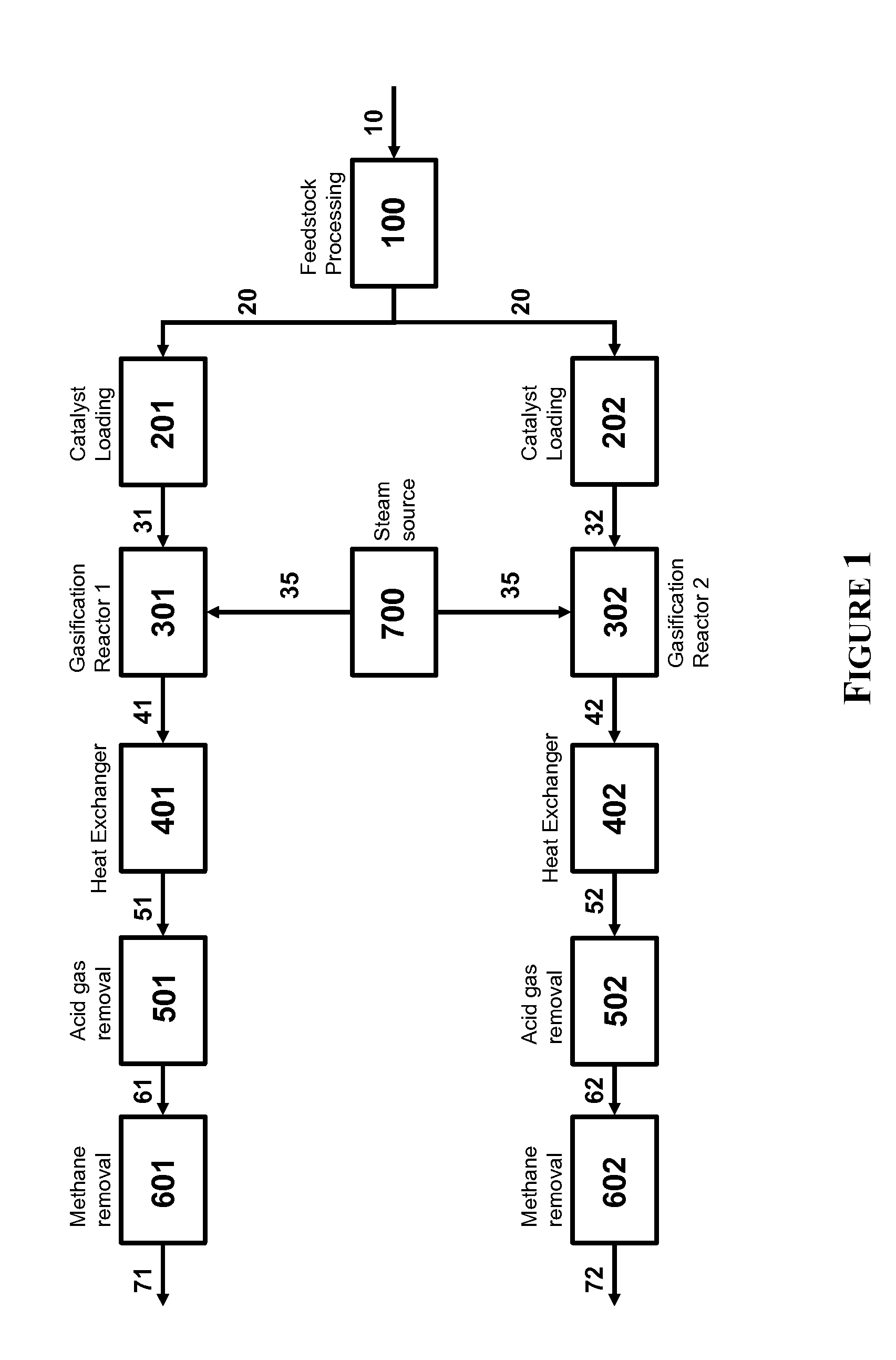
[0289]One embodiment of the system of the invention is illustrated in FIG. 1. Therein, the system comprises a single feedstock operation (100), a first (201) and second (202) catalyst loading unit, a first (301) and second (302) gasification reactor, a first (401) and second (402) heat exchanger, a first (501) and second (502) acid gas removal unit, a first (601) and second (602) methane removal unit, and a single steam source (700).
[0290]A carbonaceous feedstock (10) is provided to the feedstock processing unit (100) and is converted to a carbonaceous particulate (20) having an average particle size of less than 2500 μm. The carbonaceous particulate is provided to each of the a first (201) and second (202) catalyst loading unit wherein the particulate is contacted with a solution comprising a gasification catalyst in a loading tank, the excess water removed by filtration, and the resulting wet cakes dried with a drier to provide a first (31) and second (32) catalyzed carbonaceous f...
example 2
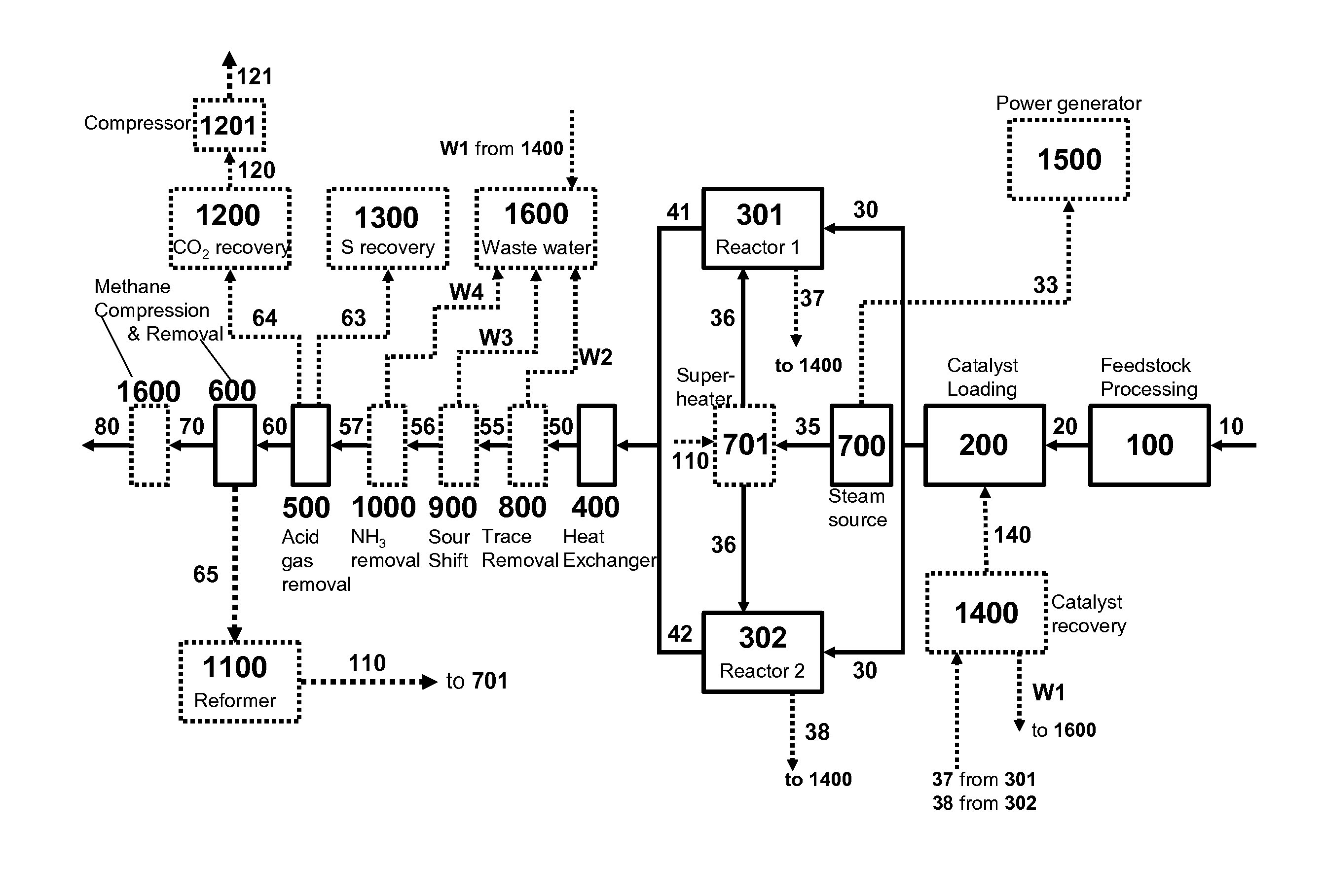
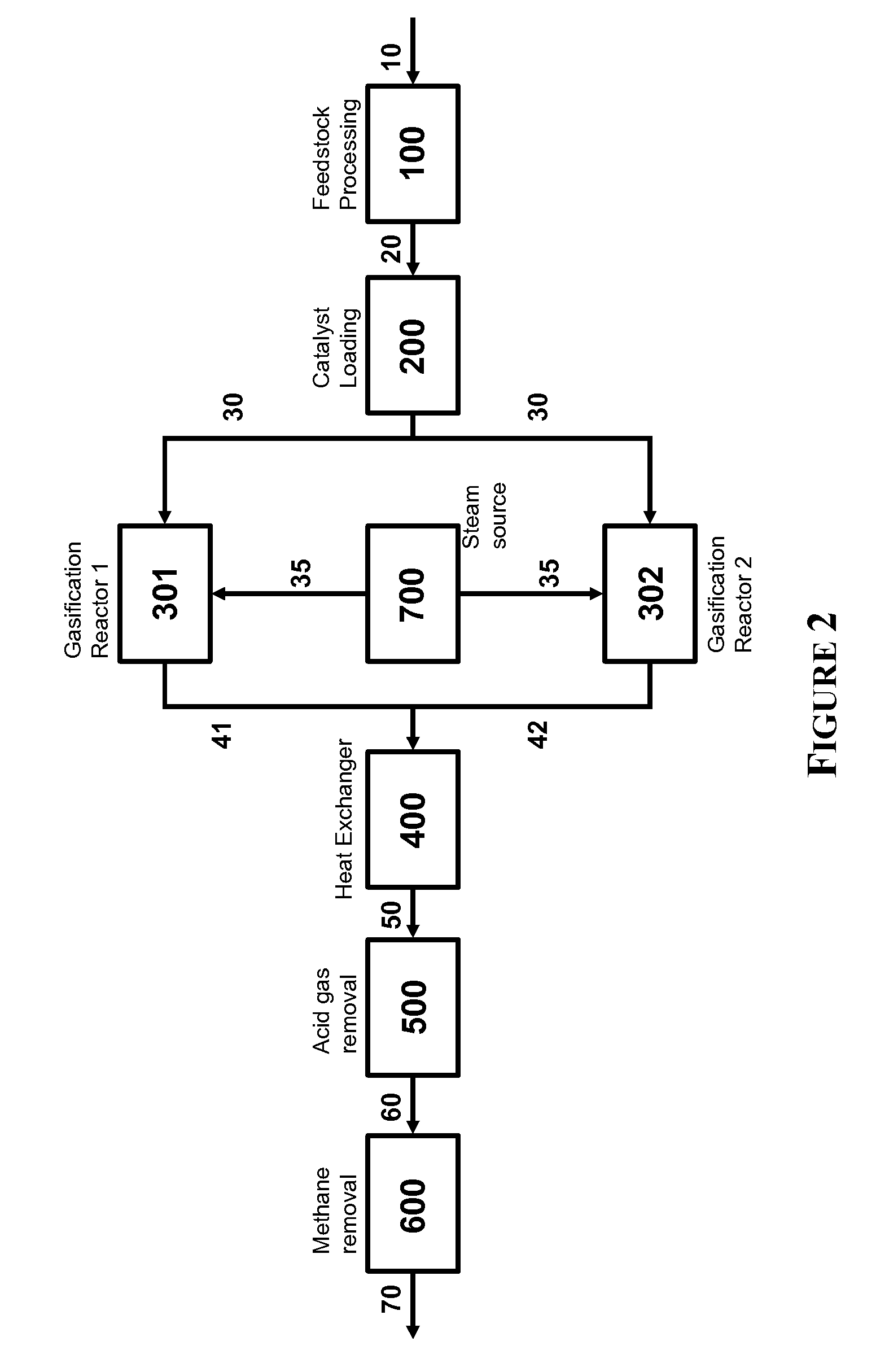
[0291]A second embodiment of the system of the invention is illustrated in FIG. 2. Therein, the system comprises a single feedstock operation (100), a single catalyst loading unit (200), a first (301) and second (302) gasification reactor, a single heat exchanger (400), a single acid gas removal unit (500), a single methane removal unit (600), and a single steam source (700).
[0292]A carbonaceous feedstock (10) is provided to the feedstock processing unit (100) and is converted to a carbonaceous particulate (20) having an average particle size of less than 2500 μm. The carbonaceous particulate is provided to the single catalyst loading unit (200) wherein the particulate is contacted with a solution comprising a gasification catalyst in a loading tank, the excess water removed by filtration, and the resulting wet cake dried with a drier to provide a catalyzed carbonaceous feedstock (30) to the first and second gasification reactors. In the two gasification reactors, the catalyzed carb...
example 3
[0293]A third embodiment of the system of the invention is illustrated in FIG. 3. Therein, the system comprises a first (101) and second (102) feedstock operation, a first (201) and second (202) catalyst loading unit, a first (301) and second (302) gasification reactor, a single heat exchanger (400), a single acid gas removal unit (500), a single methane removal unit (600), and a single steam source (700).
[0294]First (11) and second (12) carbonaceous feedstocks are provided to the first (101) and second (102) feedstock processing units, respectively, and converted to a first (21) and second carbonaceous particulate (22), each having an average particle size of less than 2500 μm. The first (21) and second (22) carbonaceous particulates are separately provided to each of the first (201) and second (202) catalyst loading unit wherein each particulate is contacted with a solution independently comprising a gasification catalyst in a loading tank, the excess water removed by filtration, ...
PUM
 Abstract
Description
Claims
Application Information
 - R&D
- Intellectual Property
- Life Sciences
- Materials
- Tech Scout
- Unparalleled Data Quality
- Higher Quality Content
- 60% Fewer Hallucinations
Browse by: Latest US Patents, China's latest patents, Technical Efficacy Thesaurus, Application Domain, Technology Topic, Popular Technical Reports.
© 2025 PatSnap. All rights reserved.Legal|Privacy policy|Modern Slavery Act Transparency Statement|Sitemap|About US| Contact US: help@patsnap.com


