Three-Train Catalytic Gasification Systems

a gasification system and catalytic technology, applied in the direction of combustible gas catalytic treatment, combustible gas purification/modification, combustible gas production, etc., can solve the problems of loss of production capacity, over- or under-burdening, efficiency loss, etc., and achieve the effect of reducing moisture conten

Inactive Publication Date: 2009-12-31
SURE CHAMPION INVESTMENT LTD
View PDF103 Cites 139 Cited by
  • Summary
  • Abstract
  • Description
  • Claims
  • Application Information

AI Technical Summary

Benefits of technology

[0020](B2) a dryer to thermally treat the catalyzed carbonaceous feedstock to reduce moisture content;

Problems solved by technology

In doing so, the loss of a single component, due to failure or maintenance, in any train can require shutting down of the entire gasification train, resulting in loss of production capacity.
Each unit in the feedstock processing and gas purification and separation systems can have differing capacities, resulting in over- or under-burdening with particular units within the overall system, losses in efficiency, and increased production costs.

Method used


Image

  • Three-Train Catalytic Gasification Systems
  • Three-Train Catalytic Gasification Systems
  • Three-Train Catalytic Gasification Systems

Examples


example 1

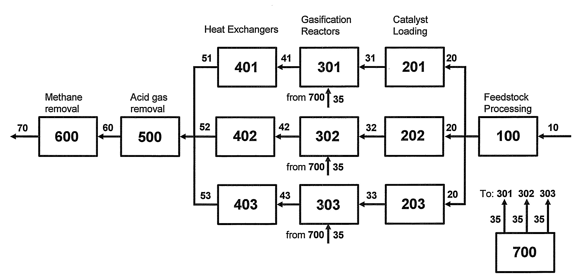
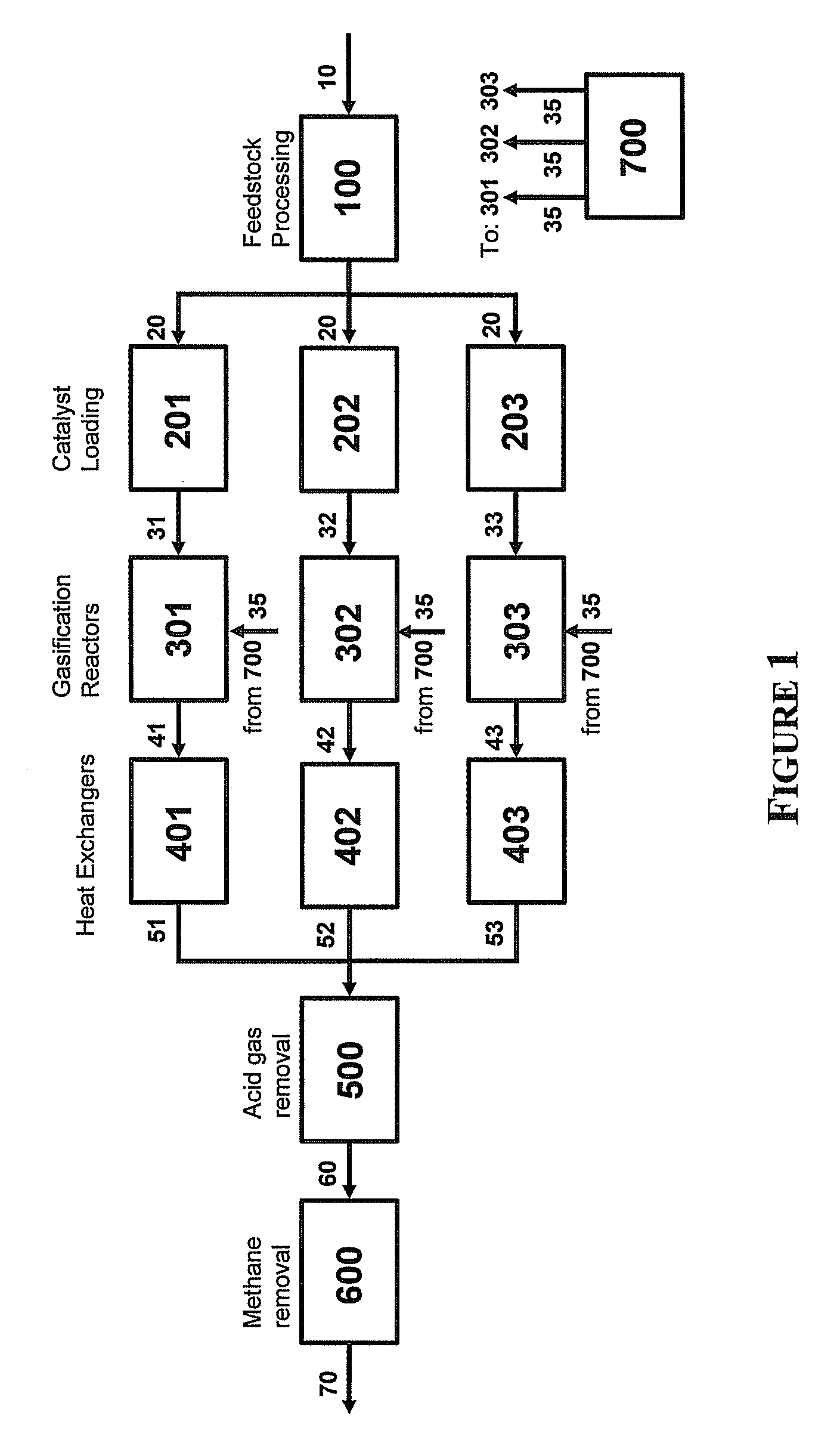
[0343]One embodiment of the system of the invention is illustrated in FIG. 1. Therein, the system comprises a single feedstock operation (100); a first (201), second (202) and third (203) catalyst loading unit; a first (301), second (302) and third (303) gasification reactor; a first (401), second (402) and third (403) heat exchanger; a single acid gas removal unit (500); a single (600) methane removal unit; and a single steam source (700).

[0344]A carbonaceous feedstock (10) is provided to the feedstock processing unit (100) and is converted to a carbonaceous particulate (20) having an average particle size of less than about 2500 μm. The carbonaceous particulate (20) is provided to each of the first (201), second (202), and third (203) catalyst loading units wherein the particulate is contacted with a solution comprising a gasification catalyst in a loading tank, the excess water removed by filtration, and the resulting wet cakes dried with a drier to provide first (31), second (32...

example 2

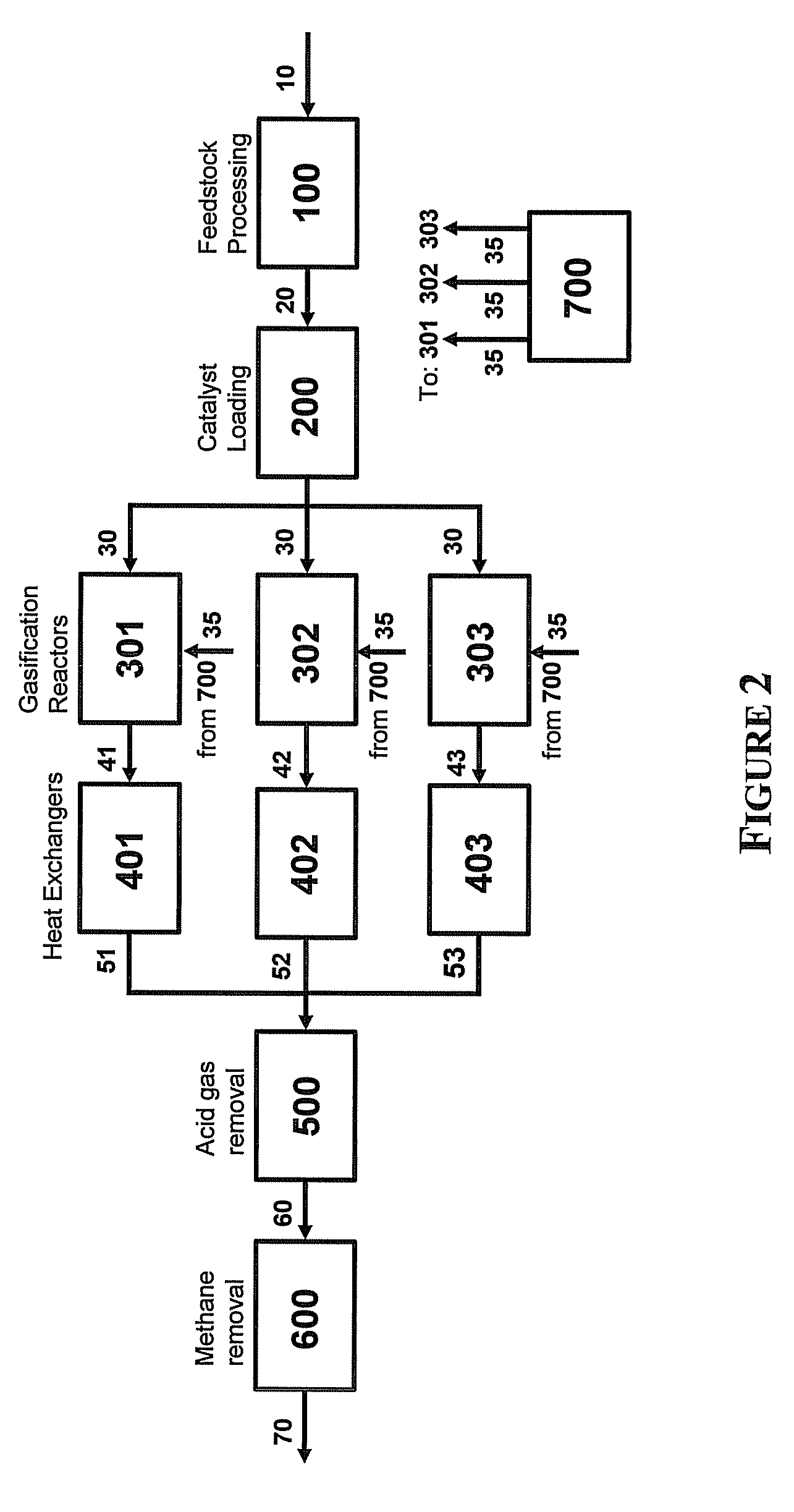
[0345]A second embodiment of the system of the invention is illustrated in FIG. 2. Therein, the system comprises a single feedstock operation (100); a single catalyst loading unit (200); a first (301), second (302) and third (303) gasification reactor; a first (401), second (402) and third (403) heat exchanger; a single acid gas removal unit (500); a single methane removal unit (600); and a single steam source (700).

[0346]A carbonaceous feedstock (10) is provided to the feedstock processing unit (100) and is converted to a carbonaceous particulate (20) having an average particle size of less than about 2500 μm. The carbonaceous particulate is provided to the single catalyst loading unit (200) wherein the particulate is contacted with a solution comprising a gasification catalyst in a loading tank, the excess water removed by filtration, and the resulting wet cake dried with a drier to provide a catalyzed carbonaceous feedstock (30) to the first (301), second (302) and third (303) ga...

example 3

[0347]A third embodiment of the system of the invention is illustrated in FIG. 3. Therein, the system comprises a single (100) feedstock operation; a first (201), second (202) and third (203) catalyst loading unit; a first (301), second (302) and third (303) gasification reactor; a first (401), second (402) and third (403) heat exchanger; a first (501) and second (502) acid gas removal unit; a single methane removal unit (600); and a single steam source (700).

[0348]A carbonaceous feedstock (10) is provided to the single (100) feedstock processing unit, and converted to a carbonaceous particulate (20) having an average particle size of less than about 2500 μm. The carbonaceous particulate (20) is provided to the first (201), second (202) and third (203) catalyst loading units wherein the particulate is contacted with a solution comprising a gasification catalyst in a loading tank, the excess water removed by filtration, and the resulting wet cake dried with a drier to provide catalyz...


PUM


Abstract

Systems to convert a carbonaceous feedstock into a plurality of gaseous products are described. The systems include, among other units, three separate gasification reactors for the gasification of a carbonaceous feedstock in the presence of an alkali metal catalyst into the plurality of gaseous products including at least methane. Each of the gasification reactors may be supplied with the feedstock from a single or separate catalyst loading and/or feedstock preparation unit operations. Similarly, the hot gas streams from each gasification reactor may be purified via their combination at a heat exchanger, acid gas removal or methane removal unit operations. Product purification may comprise trace contaminant removal units, ammonia removal and recovery units, and sour shift units.

Description

CROSS REFERENCE TO RELATED APPLICATIONS[0001]This application claims priority under 35 U.S.C. § 119 from U.S. Provisional Application Ser. No. 61 / 076,440 (filed Jun. 27, 2008), the disclosure of which is incorporated by reference herein for all purposes as if fully set forth.[0002]This application is related to commonly owned and concurrently filed U.S. patent application Ser. No. ______, attorney docket no. FN-0034 US NP1, entitled TWO-TRAIN CATALYTIC GASIFICATION SYSTEMS; Ser. No. ______, attorney docket no. FN-0036 US NP1, entitled FOUR-TRAIN CATALYTIC GASIFICATION SYSTEMS; Ser. No. ______, attorney docket no. FN-0037 US NP1, entitled FOUR-TRAIN CATALYTIC GASIFICATION SYSTEMS; and Ser. No. ______, attorney docket no. FN-0038 US NP1, entitled FOUR-TRAIN CATALYTIC GASIFICATION SYSTEMS, the disclosures of which are incorporated by reference herein for all purposes as if fully set forth.FIELD OF THE INVENTION[0003]The present invention relates to systems configuration having three ca...

Claims


Application Information

Patent Timeline
Patent Type & Authority Applications(United States)
IPC IPC(8): B01J8/00
CPCC10J3/00C10L3/08C10J3/721C10J2300/0903C10J2300/0906C10J2300/093C10J2300/0973C10J2300/0986C10J2300/1662C10J2300/1671C10J2300/1675C10J2300/1687C10J2300/169C10J2300/1807C10J2300/1823C10J2300/1853C10J2300/1884C10K1/002C10K1/003C10K1/004C10K1/006C10K1/007C10K1/101C10K1/102C10K1/103C10K1/14C10K1/143C10K1/16C10K1/165C10K1/20C10K1/32C10K3/04C10J3/482
Inventor ROBINSON, EARL T.LAU, FRANCIS S.DODSON, DWAIN
Owner SURE CHAMPION INVESTMENT LTD
Why Eureka
Try Eureka