Lead acid storage battery

a technology of lead acid storage and battery body, which is applied in the direction of cell components, cell component details, vent arrangements, etc., can solve the problems of deteriorating and affecting the life performance of the battery. , to achieve the effect of improving the life performance of the battery

Active Publication Date: 2009-12-31
GS YUASA INT LTD
View PDF2 Cites 8 Cited by
  • Summary
  • Abstract
  • Description
  • Claims
  • Application Information

AI Technical Summary

Benefits of technology

[0024]According to the present invention, the heights of the liquid surface can be uniformed among cells, thereby improving the life performance of the battery.

Problems solved by technology

However, when the lead acid storage battery of collective exhaust system is used, for example, in an engine room, and when comparing the cells in both ends which are easily affected by heat generated from the engine with other cells (hereinafter referred to as “intermediate cell”) not easily affected by heat generation, a fall of the liquid surface occurs in the cells in both ends more easily than in the intermediate cells.
In a lead acid storage battery, there has been a problem that, with variation in the height of the liquid surface between cells, the life in a cell of low liquid surface height becomes shorter, thereby deteriorating the life performance as a battery.

Method used


Image

  • Lead acid storage battery
  • Lead acid storage battery
  • Lead acid storage battery

Examples


embodiment 1

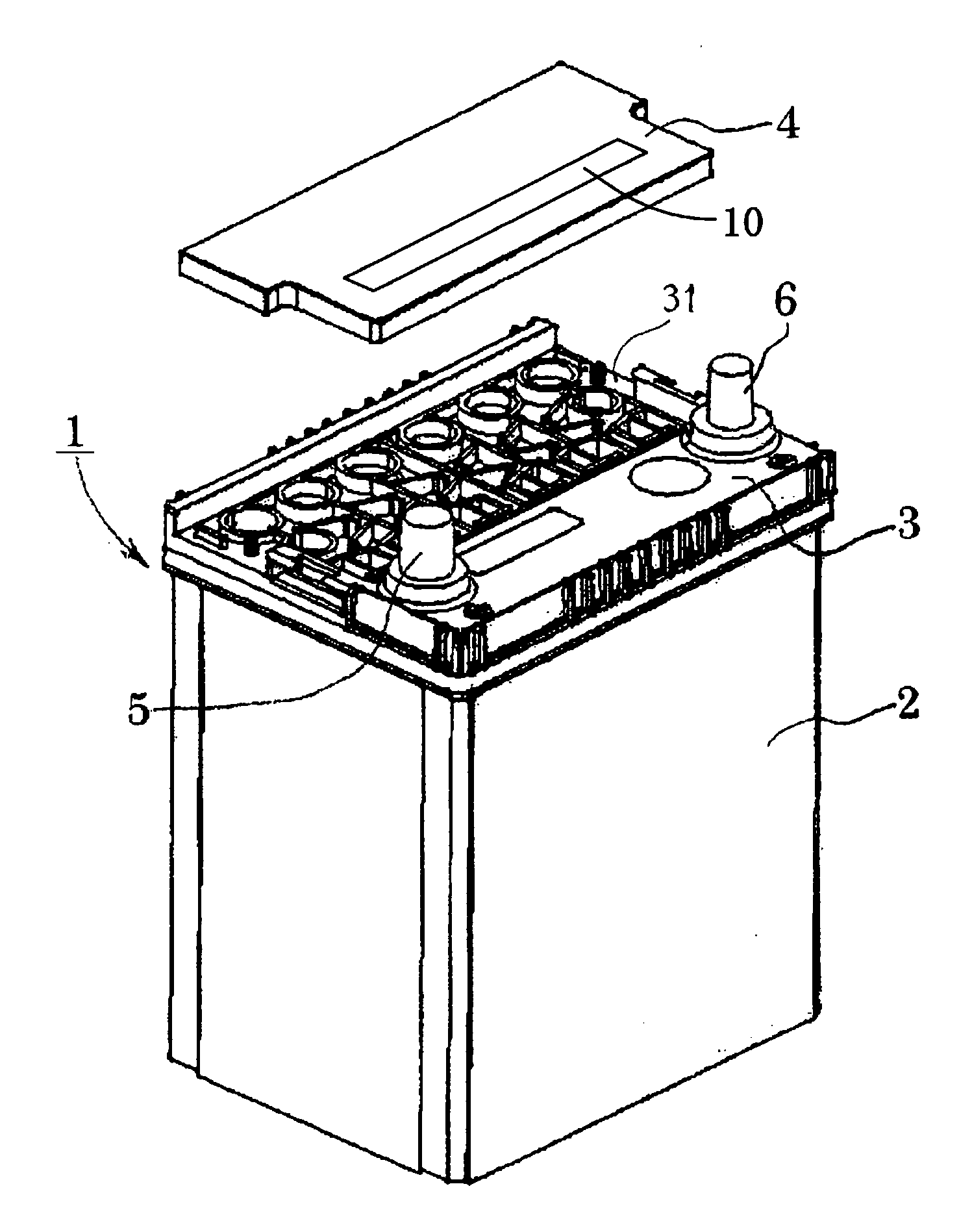
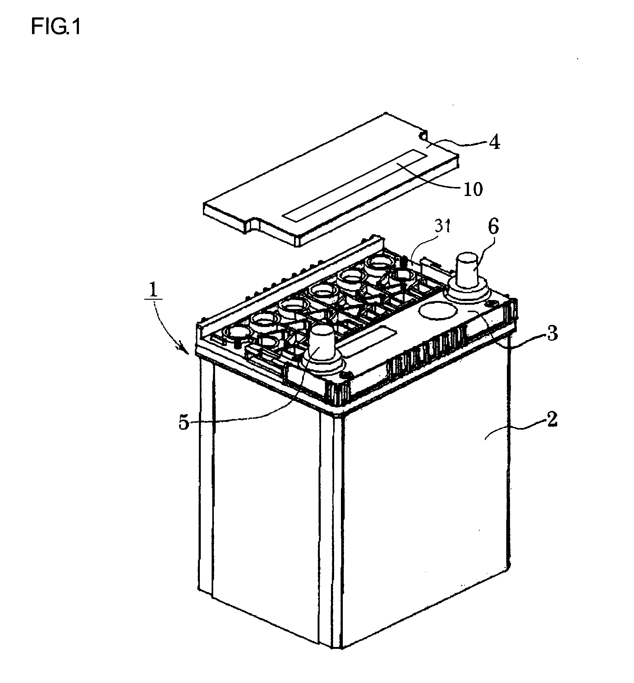
[0058]In what follows, an lead acid storage battery of Embodiment 1 according to one embodiment of the present invention is explained, however, the present invention is not limited to this. FIG. 1 is a perspective view viewed obliquely from above showing a state of a lead acid storage battery 1 of 6 cells mono-block type according to one embodiment of the present invention, with an upper lid 4 removed. Inside of a battery container 2 in the lead acid storage battery 1 is divided into 6 cells by 5 partitions (not shown) arranged in parallel on the short side, and each cell is housing an electrode plate group composed of a positive electrode plate, a negative electrode plate, and a separator, and an electrolyte composed of diluted sulfuric acid (not shown).

[0059]A middle lid 3 is attached over the battery container 2, while the upper lid 4 is attached to a recessed portion 31 in the middle lid 3. Any of the battery container 2, the middle lid 3, and the upper lid 4 are a molded body m...

example 1

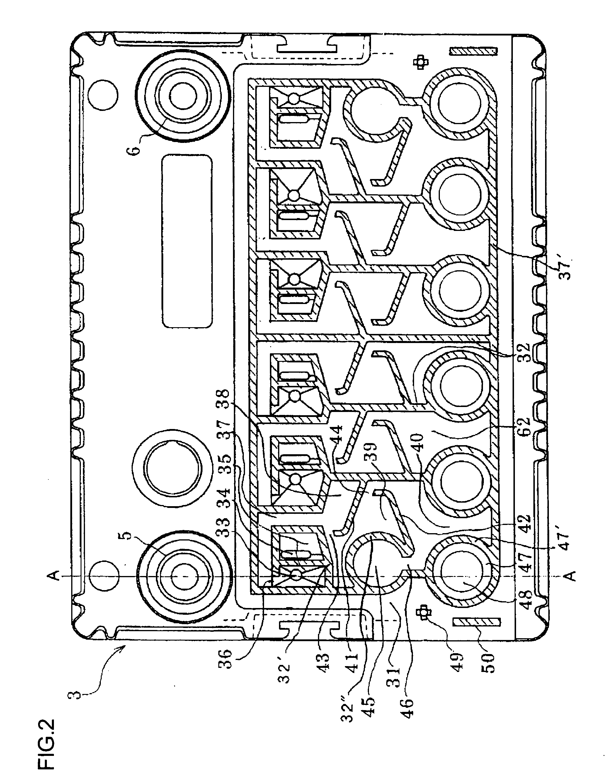
[0078]As shown in FIGS. 1 and 5A, a high thermal conduction member 10 is placed on the upper surface of the upper lid 4. The placing position is not particularly limited, however, the high thermal conduction member 10 is preferred to be provided in the above of the cell-interconnecting small chamber 35. This allows the electrolyte mist and moisture vapor included in the gas discharged from the gas discharging port 34 to be dew-condensed in an early stage and to recirculate within the cell from the electrolyte recirculating port 33, and thus, the electrolyte mist and moisture vapor in the gas in a process of moving from the exhaust chamber 37 to the concentration exhaust chamber 45 can be reduced, thereby contributing to prevent the clogging of the porous filter 63.

[0079]Additionally, the high thermal conduction member 10 is provided in apart of the upper lid 4, with intention to obtain the most effective position on the upper surface in view of cost and weight, and thus, the entire ...

example 2

[0081]FIG. 5B shows the high thermal conduction member 10 placed in the peripheral edge (the longer side of the battery) of the middle lid 3 having the recessed portion 31 formed therein. In this case, the placing position is also not particularly limited, however, as can be clearly seen from FIG. 1, the high thermal conduction member 10 is placed in the long side only because it is constitutionally difficult to place in the short side of the battery. When it is constitutionally possible, the high thermal conduction member 10 may be placed in both sides, or only in the short side. The present example allows the heat transmission from the outside of the battery to the recessed portion to be suppressed, thereby uniforming the temperature of the recessed portion corresponding to each cell. Consequently, a problem that the gas leaked out of a cell is dew-condensed in another cell and recirculates in the cell can be prevented from occurring.


PUM

PropertyMeasurementUnit
lengthaaaaaaaaaa
widthaaaaaaaaaa
thicknessaaaaaaaaaa

Abstract

A lead acid storage battery according to the present invention comprises a battery container for housing a plurality of cells, a middle lid for covering the battery container, and an upper lid for covering the middle lid, wherein, on the upper surface of the middle lid, a gas discharging port for discharging the gas generated inside of the cell and an electrolyte recirculating port for recirculating the moisture to be discharged along with the gas within the cell are formed as corresponding to each cell. A plurality of exhaust chambers separated by an exhaust chamber partition are formed in a space surrounded by the middle lid and the upper lid, and a mechanism for collectively exhausting the gas discharged from the gas discharging port to the outside of the battery by interconnecting the plurality of exhaust chambers is comprised.

Description

TECHNICAL FIELD[0001]The present invention relates to a lead acid storage battery comprising an exhaust structure for exhausting gas while preventing leakage of electrolyte.BACKGROUND ART[0002]As an exhaust structure of a mono-block type lead acid storage battery which comprises a plurality of cells, there roughly are an individual exhaust system with an exhaust plug provided in each cell and a collective exhaust system for once leading the gas exhausted from each cell into an exhaust chamber and then exhausting it into the outside. In view of the advantages, such as needing less number of parts compared with the individual exhaust system, allowing the volume in an upper space of an electrode plate to decrease, allowing the battery to be downsized without reducing its volume, and allowing the leakage amount of electrolyte to be suppressed, the collective exhaust system has been broadly employed for on-vehicle lead acid storage batteries.[0003]Conventionally, with respect to a lead a...

Claims


Application Information

Patent Timeline
Patent Type & Authority Applications(United States)
IPC IPC(8): H01M2/12H01M50/103H01M50/147H01M50/367H01M50/627
CPCH01M2/024H01M2/043H01M2/1247H01M2/1252H01M2/36Y02E60/126H01M10/5004H01M10/5016H01M10/5032H01M10/5046H01M10/12H01M10/625H01M10/647H01M10/6551H01M10/613Y02E60/10H01M50/147H01M50/383H01M50/367H01M50/103H01M50/627H01M50/30H01M50/35H01M50/10H01M50/60
Inventor SAITO, KAZUMAHIRAKAWA, KENJIKIRIBAYASHI, MOTOSHI
Owner GS YUASA INT LTD
Why Eureka
Try Eureka