

Stent
- Summary
- Abstract
- Description
- Claims
- Application Information
AI Technical Summary
Benefits of technology
Problems solved by technology
Method used
Image

Examples
embodiment 1
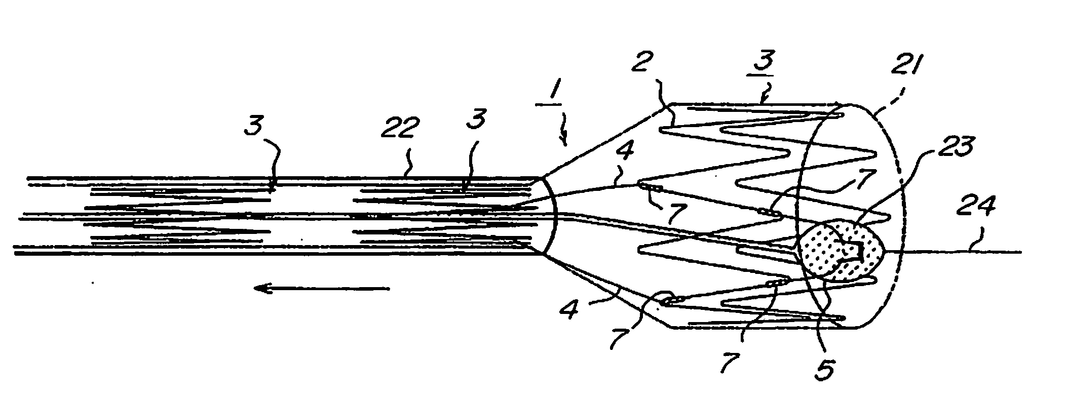
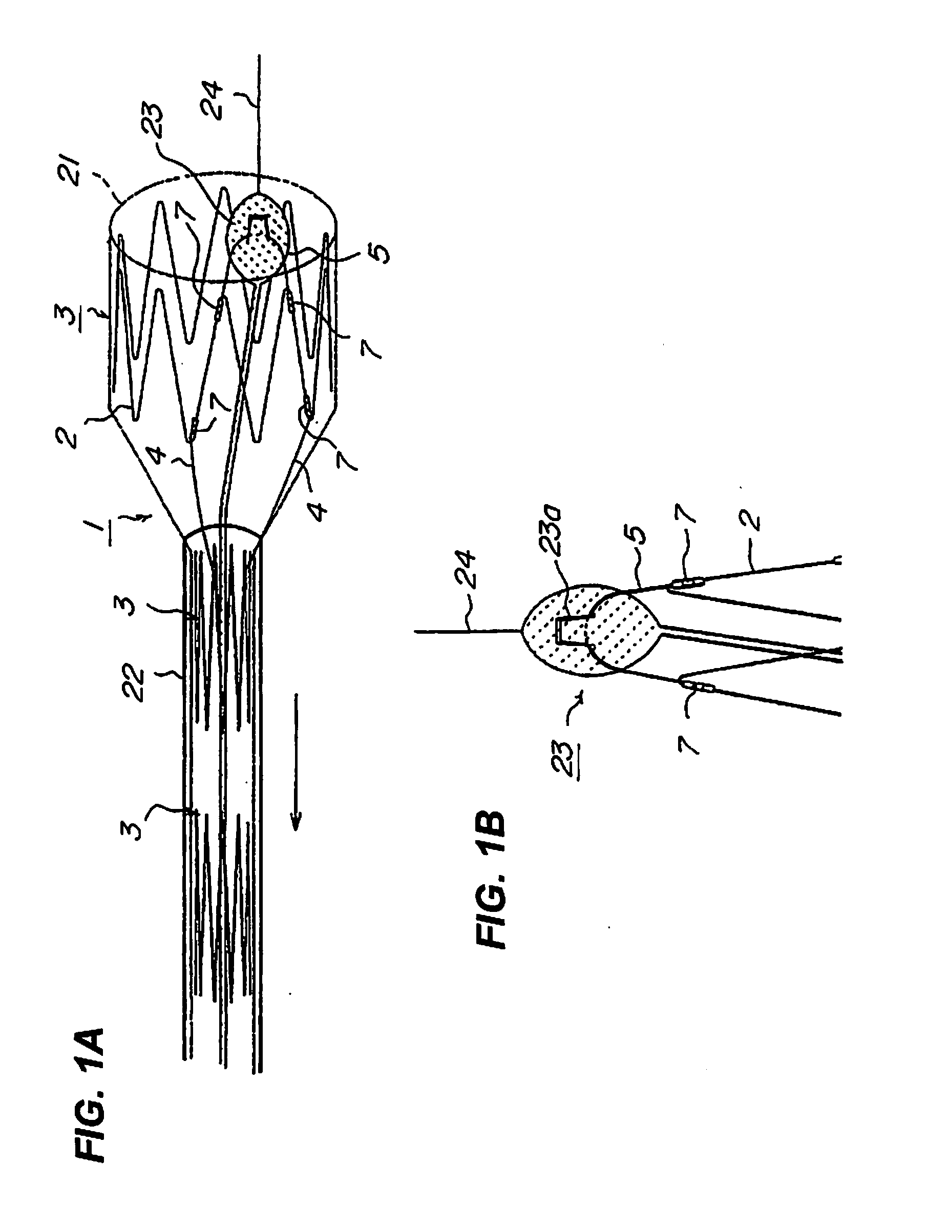
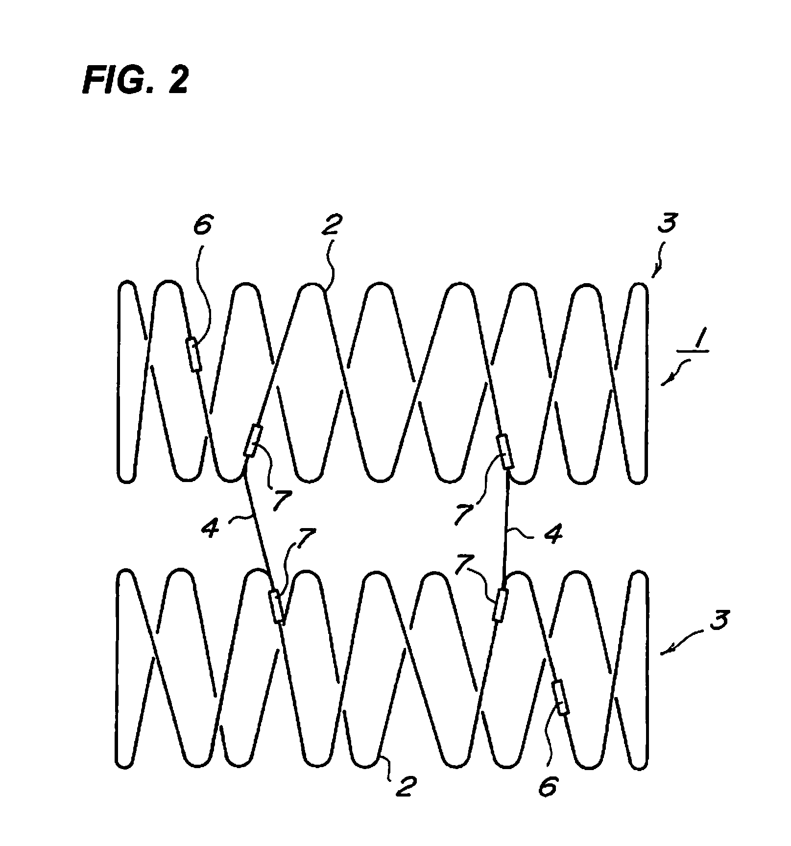
[0071]Next, an embodiment of a stent according to the present invention will be described with reference to the drawings. FIG. 1 are diagrams for describing a relation between a sheath and a stent constituted by connecting a plurality of loop stents with each other through a strut. FIG. 2 is a diagram for describing a relation between the strut and the loop stent whose diameter is increased. FIG. 3 is a diagram for describing a structure of a connection part.
[0072]As shown in FIGS. 1 and 2, a stent 1 according to this embodiment is constituted as a complex stent in which a stent main wire 2 is bent in a zigzag form, end surfaces of a stent main wire 2 butted against each other and welded, thereby disposing a plurality of loop stents 3 formed into a loop in series, and these loop stents 3 are connected to each other through at least two struts 4. A stabilizer hook 5 is connected to one of the top loop stent 3.
[0073]At a butt welded portion of the stent main wire 2 of the loop stent 3...
embodiment 2
[0096]Next, another embodiment of the locking part formed on the strut 4 in the connection part constituted in the stent 1 will be described with reference to FIG. 4. In the stent of the invention, a structure thereof (structures of the loop stent 3 and the strut 4) other than the shape and structure of the locking part in the connection part is the same. Therefore, the structure of the connection part will be described.
[0097]In FIG. 4(a), a swelling portion 12 is formed on the end 4a of the strut 4, and the swelling portion 12 constitutes the locking part. The swelling portion 12 can be formed by presswork. If a diameter of the junction pipe 7 is selected, the junction pipe 7 can be formed before the strut 4 is inserted into the junction pipe 7.
[0098]When the locking part including the swelling portion 12 is formed on the end 4a of the strut 4, the swelling portion 12 abuts against the end surface of the junction pipe 7 and is locked to the end surface, and even when a force in the...
embodiment 3
[0103]Next, another embodiment of the locking part formed on the strut 4 in the connection part constituted in the stent 1 will be described with reference to FIG. 5. In the stent 1 of this embodiment, a structure of the locking part is different from those of the previous embodiments, and the shape of the strut 4 is not varied.
[0104]FIG. 5(a) shows that the junction pipe 7 is inserted into the stent main wire 2 constituting the loop stent 3, the strut 4 is inserted into the junction pipe 7 and they are caulked. Then, the junction pipe 7 and the strut 4 are welded to each other, and this weld point 14 functions as the locking part.
[0105]The junction pipe 7 and the strut 4 may be welded by spot welding or laser welding, and any of which can preferably be utilized. When such a welding method is employed, the weld point 14 passing through the junction pipe 7, the strut 4 and the stent main wire 2 can be formed by selecting the welding direction, or a weld point 14 passing through the j...
PUM
 Abstract
Description
Claims
Application Information