
Virtual tape device, data backup method, and recording medium

Inactive Publication Date: 2009-12-31
NEC CORP
View PDF0 Cites 17 Cited by
  • Summary
  • Abstract
  • Description
  • Claims
  • Application Information

AI Technical Summary

Benefits of technology

[0013]It is therefore an exemplary object of the present invention to reduce the power consumption in a virtual tape device, and to provide a virtual tape device, a data backup method, and a recording medium, which can extend the product life of the virtual tape device itself.

Problems solved by technology

Recently, the power consumption amount has become an issue since there has been a demand to cut the operating cost (TCO).
Normally, in a storage device such as a magnetic disk array device employed in the above-mentioned virtual tape device, the power consumption amount increases in proportional to the storage capacity.
Normally, when on / off operations of the power in the magnetic device are repeated, a failure rate thereof becomes increased.
Therefore, in the backup system using the MAID technique, the frequency of supplying the power to the magnetic disk device is limited.
This may shorten the product life of the storage device itself.

Method used


Image

  • Virtual tape device, data backup method, and recording medium
  • Virtual tape device, data backup method, and recording medium
  • Virtual tape device, data backup method, and recording medium

Examples


first exemplary embodiment

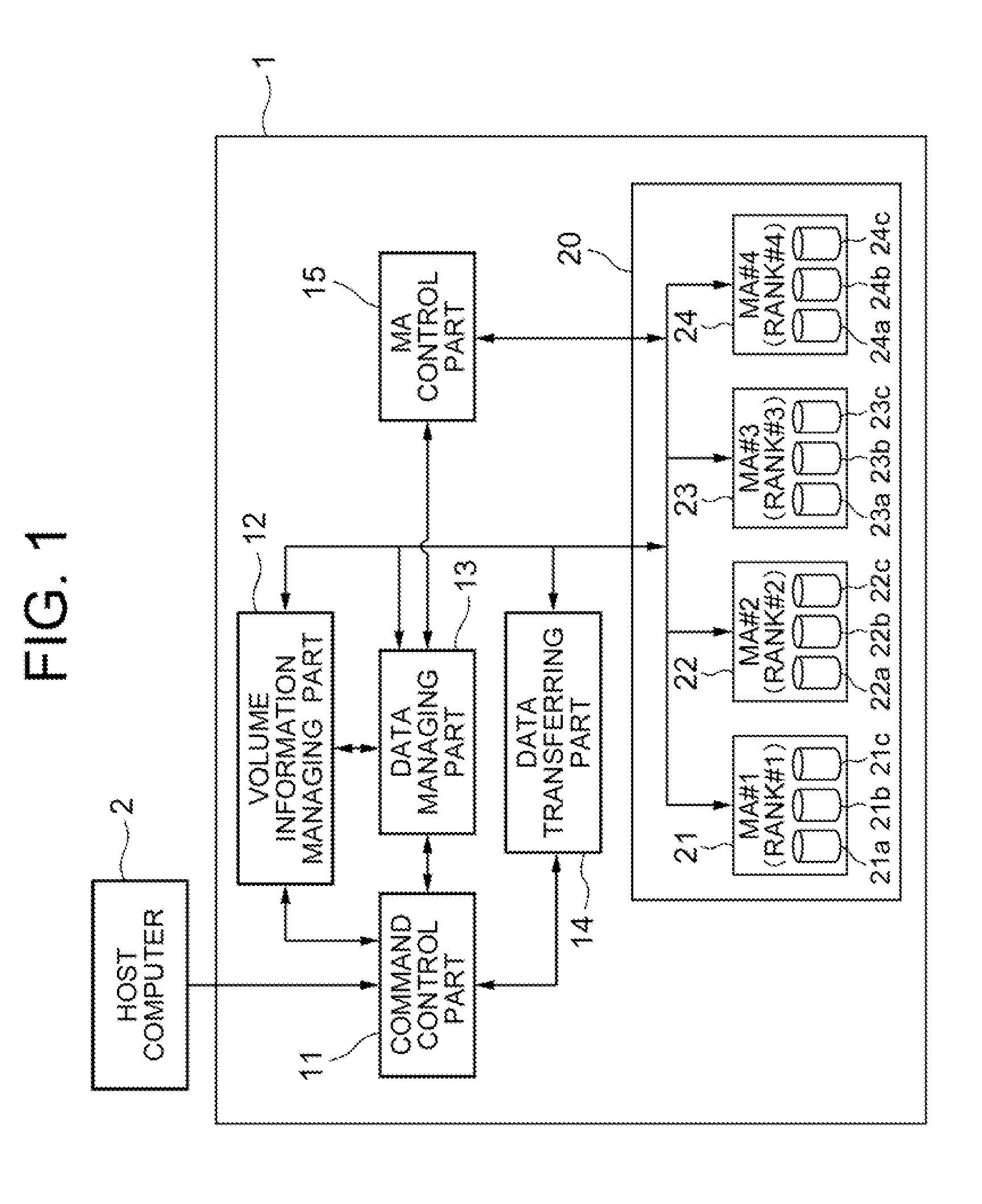
[0048]As shown in FIG. 1, the virtual tape device 1 according to the first exemplary embodiment of the invention has a volume information managing part 12 and a data managing part 13 in order to manage the data, which is supposed to be executed by the host computer 2 with the magnetic tape device, with the magnetic disk device virtually i.e., manage the data from the host computer 2 not with the magnetic tape device but with the disk database by using two or more magnetic disk devices while keeping such an operation mode that data management is executed by the host computer 2 with the magnetic tape devices.

[0049]Further, the magnetic disk devices 21a, 21b, 21c-24a, 24b, 24c included in the disk array group 20 are divided into an information management magnetic disk group whose power is kept to an on-state at all times and to two or more recording disk groups where the data is managed. In the case of FIG. 1, the information managing disk group contains the magnetic disk devices 21a, ...

second exemplary embodiment

[0091]Next, a case of managing data by separating volume labels from the data (backup data, for example) to be managed in the first exemplary embodiment will be described as a second exemplary embodiment of the invention.

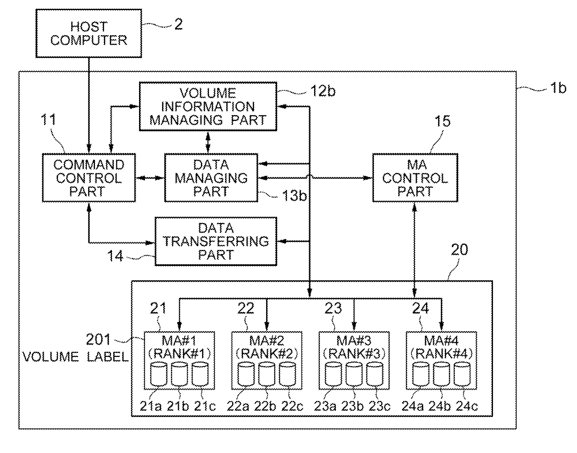
[0092]FIG. 4 is a conceptual diagram showing the structure of the virtual tape device 1b according to the second exemplary embodiment of the invention. Compared with the virtual tape device 1 according to the first exemplary embodiment of the invention shown in FIG. 1, the virtual tape device 1b of the second exemplary embodiment has different functions regarding a volume information managing part 12b and a data managing part 13b as those of the virtual tape device 1. Further, the recording positions of a part of data are different (will be described in detail later). Except for those, the structural elements and the functions are the same as those of the first exemplary embodiment. Thus, only the different points from those of the first exemplary embodiment will be...

third exemplary embodiment

[0108]FIG. 8 is a conceptual diagram showing the structure of a virtual tape device 1c according to a third exemplary embodiment of the invention. Compared with the virtual tape device 1 according to the first exemplary embodiment of the invention shown in FIG. 1 and the virtual tape device 1b according to the second exemplary embodiment of the invention shown in FIG. 4, the virtual tape device 1c of the third exemplary embodiment has different functions regarding a volume information managing part 12c and a data managing part 13c as those of the virtual tape device 1. Further, the recording positions of a part of data are different (will be described in detail later). Except for those, the structural elements and the functions are the same as those of the first exemplary embodiment. Thus, only the different points from those of the first and second exemplary embodiments will be described hereinafter.

[0109]With the virtual tape device 1b according to the second exemplary embodiment ...


PUM


Abstract

To provide a virtual tape device to reduce power consumption by utilizing a disk array device conforming to MAID. Two or more disk devices are divided into an information managing disk group whose power is kept on at all times and to two or more recording disk groups whose power is turned on / off as necessary when managing data. The virtual tape device includes: a volume information managing part which manages positions of virtual tapes allotted to storage areas of the recording disk groups; and a data managing part which rearranges, in the recording disk group whose power is on, the virtual tape for storing the data to the recording disk group whose power is off based on writing / reading information stored in the information managing disk group and positional information of the virtual tapes, and executes a control to write backup data to the recording disk group whose power is on.

Description

CROSS-REFERENCE TO RELATED APPLICATION[0001]This application is based upon and claims the benefit of priority from Japanese patent applications No. 2008-167273, filed on Jun. 26, 2008, and No. 2009-144912, filed on Jun. 18, 2009, the disclosure of which is incorporated herein in its entirety by reference.BACKGROUND OF THE INVENTION[0002]1. Field of the Invention[0003]The present invention relates to a virtual tape device used for backup in a computer device and, more specifically, to a technique which can reduce the number of startup actions in addition to reducing the power consumption of the virtual tape device.[0004]2. Description of the Related Art[0005]In accordance with increased data amount in computer systems, the storage capacitance thereof has become increased. This induces more and more increase in the importance in data backup. There has been developed a virtual tape device as depicted in Japanese Unexamined Patent Publication 2006-260392 (Patent Document 1), which uses,...

Claims


Application Information

Patent Timeline
IPC IPC(8): G06F12/00G06F12/16
CPCG06F1/3203G06F1/3268Y02B60/1246G06F3/0634G06F3/0686G06F3/0625Y02D10/00
Inventor NONAKA, HAJIMEMORI, YOSHIAKINAKAJIMA, MAKOTOYOSHIKAWA, MUNEYUKI
Owner NEC CORP
Learn More