Method of taking off auxiliary power from an airplane turbojet, and a turbojet fitted to implement such a method

a technology of airplane turbojet and auxiliary power, which is applied in the direction of rotors, marine propulsion, vessel construction, etc., can solve the problems of reducing the efficiency of low pressure turbines and slowing down the turning speed, so as to avoid an increase in engine thrust

Active Publication Date: 2010-01-07
SN DETUDE & DE CONSTR DE MOTEURS DAVIATION S N E C M A
View PDF9 Cites 10 Cited by
  • Summary
  • Abstract
  • Description
  • Claims
  • Application Information

AI Technical Summary

Benefits of technology

[0010]An engine computer enables these parameters to be varied as a function of the speed of the engine and of electrical power requirements. Thus, it is possible to avoid an increase in engine thrust (by using a controlled loss in the efficiency of the lo

Problems solved by technology

Thus, the efficiency of the low pressure turbine is reduced so that it is cause

Method used


Image

  • Method of taking off auxiliary power from an airplane turbojet, and a turbojet fitted to implement such a method
  • Method of taking off auxiliary power from an airplane turbojet, and a turbojet fitted to implement such a method

Examples


Embodiment Construction

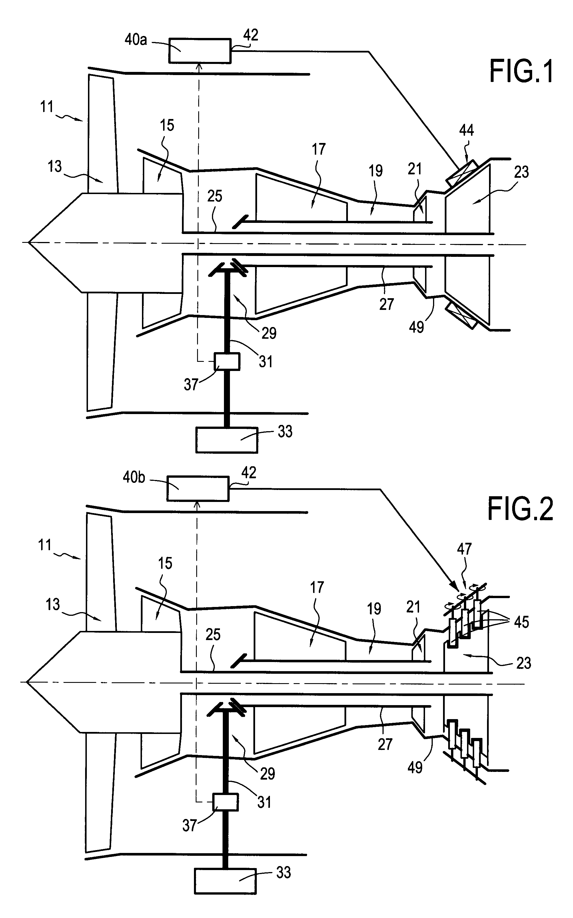
[0019]The two embodiments shown diagrammatically respectively in FIGS. 1 and 2 can be combined by providing a computer suitable for controlling the two systems that are liable to modify the efficiency of the low pressure turbine.

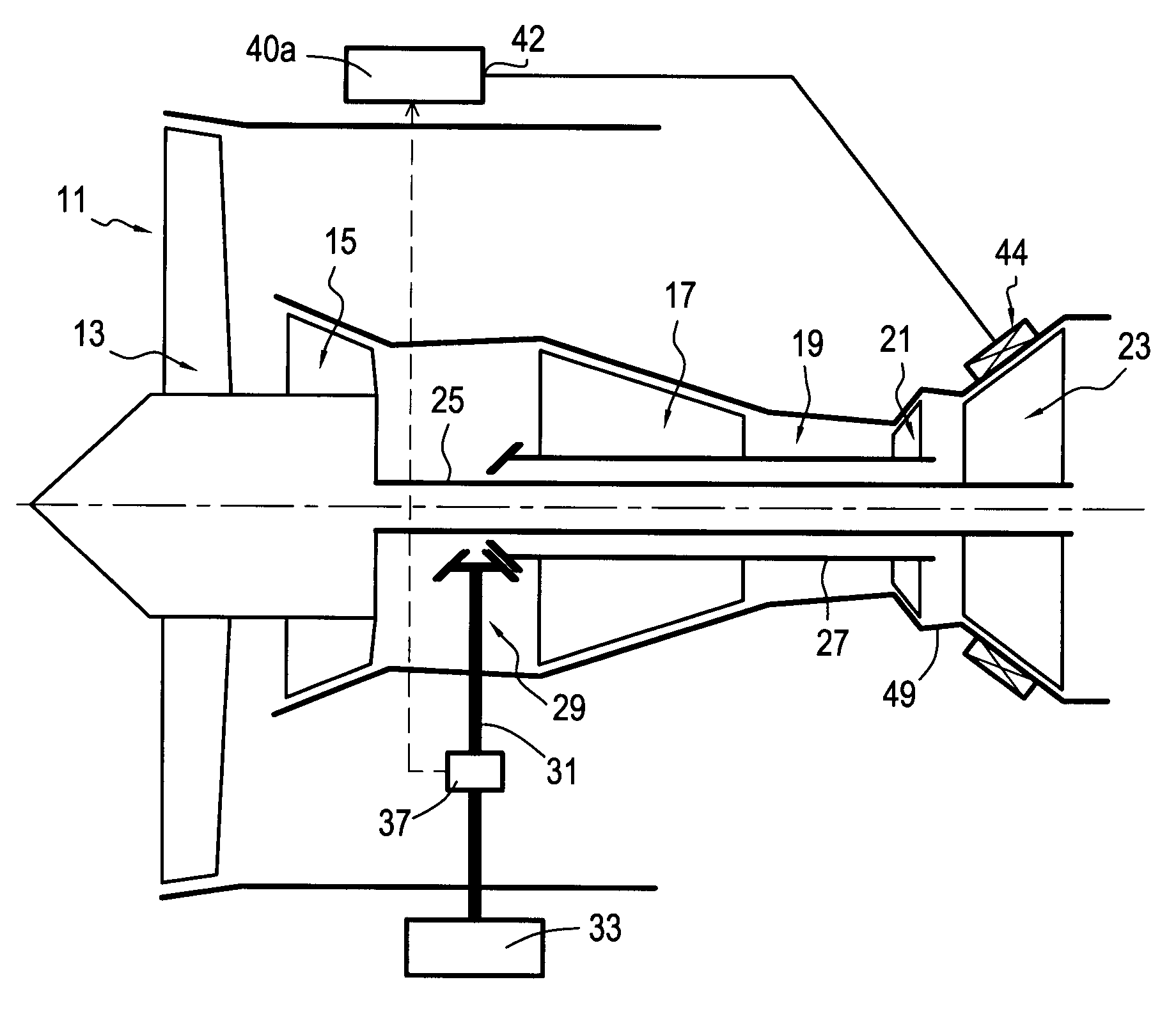
[0020]The bypass turbojet 11 shown in FIG. 1 comprises in conventional manner, from upstream to downstream: a fan 13; a low pressure compressor 15; a high pressure compressor 17; a combustion chamber 19; a high pressure turbine 21; and a low pressure turbine 23. The low pressure turbine 23 is mechanically connected to an axial shaft 25 driving both the fan 13 and the low pressure compressor 15. The high pressure turbine 21 is connected to an axial shaft 27 driving, in particular, the high pressure compressor 17. This subassembly is referred to as the high pressure spool. The shaft 27 is mechanically coupled to a mechanical transmission system 29 having a radial shaft 31 driving an electricity generator 33 via appropriate stepdown gearing.

[0021]Nowadays, the ...


PUM


Abstract

Producing the electrical power need for equipment on board an airplane. Auxiliary power is taken off by means of a shaft driven by the high pressure turbine and, when idling, the efficiency of the low pressure turbine is degraded so as to enable the high pressure turbine to operate at a speed that is sufficient for delivering the required auxiliary power.

Description

[0001]The invention relates to producing the auxiliary power needed by equipment on board an airplane, the power being taken from the turbojet(s) of said airplane.BACKGROUND OF THE INVENTION[0002]In recent airplanes, electrical power requirements are becoming ever greater. Ever more powerful electricity generators are being used. Such an electricity generator is driven by a turbojet of the airplane. It is known to take off the required mechanical power from the shaft that is associated with the high pressure turbine. More particularly, a radial shaft is mechanically coupled to the axial shaft associated with said high pressure turbine, and said power is delivered to a gearbox that drives the electricity generator. When a large amount of electrical power is required, that solution gives rise to difficulties when the engine is idling, whether on the ground or in flight, because of the high level of torque required to drive the electricity generator. This torque tends to cause the high...

Claims


Application Information

Patent Timeline
IPC IPC(8): F02C9/00F02C6/04F01D7/00
CPCF02C7/32F05D2270/023F02C9/22F02C7/36
Inventor COLOTTE, BAPTISTE BENOITGALIVEL, JEAN PIERREZSIGA, ZOLTAN
Owner SN DETUDE & DE CONSTR DE MOTEURS DAVIATION S N E C M A
Why Eureka
Try Eureka