Supercharger

a supercharger and supercharger technology, applied in the direction of positive displacement liquid engines, piston pumps, liquid fuel engines, etc., can solve the problems of product failure, significant power loss, and excessive lubricating oil thrown onto, and achieve adequate lubrication of gears and associated bearings, and reduce power loss and temperature elevation of lubricant. , the effect of reducing the temperature of the lubrican

Active Publication Date: 2010-01-07
VORTECH ENG
View PDF13 Cites 14 Cited by
  • Summary
  • Abstract
  • Description
  • Claims
  • Application Information

AI Technical Summary

Benefits of technology

[0003]Briefly, the present invention, in a preferred embodiment, comprises a supercharger having an internal lubrication reservoir, a drive gear mounted on a drive shaft above the reservoir, an impeller, an impeller gear mounted on an impeller shaft below the drive gear that engages the drive gear to effect stepped up rotation of said impeller in response to rotation of the drive shaft, bearing assemblies, an oil slinger mounted on the impeller shaft adjacent to the impeller gear for rotation therewith such that the oil slinger projects radially beyond the impeller gear and at least a lower portion thereof is submerged within the lubrication fluid in the reservoir and a baffle assembly proximate the gears and oil slinger for controlling the flow of lubricating oil. The baffle assembly limits the amount of oil directed by the slinger onto the gears and associated bearing assemblies, limits oil splash onto the gears from the oil reservoir, strips excess oil from the drive and impeller gears that is entrained on the perimeter thereof during rotation of the gears and directs oil back to the lubrication reservoir whereby the aforesaid power losses and temperature elevation of the lubricant are substantially reduced while maintaining adequate lubrication of the gears and associated bearings. A lightweight, foaming resistant oil is preferably employed in the preferred embodiment of the present invention.

Problems solved by technology

While such internal lubricating systems have several cost advantages over external systems, it has been found that during operation, these rapidly rotating oil slingers tend to throw an excessive volume of lubricating oil onto the gears and bearing assemblies inside the transmission case.
The result of the entrained oil carried by the meshing gears in a supercharger is a significant power loss due to the shearing of the viscous lubricant film and resistance to rotation created by the large volume of lubricating oil engaging the mechanical components.
Also, a significant rise in the temperature of the oil within the internal reservoir results which can ultimately lead to product failure.

Method used


Image

  • Supercharger
  • Supercharger
  • Supercharger

Examples


Embodiment Construction

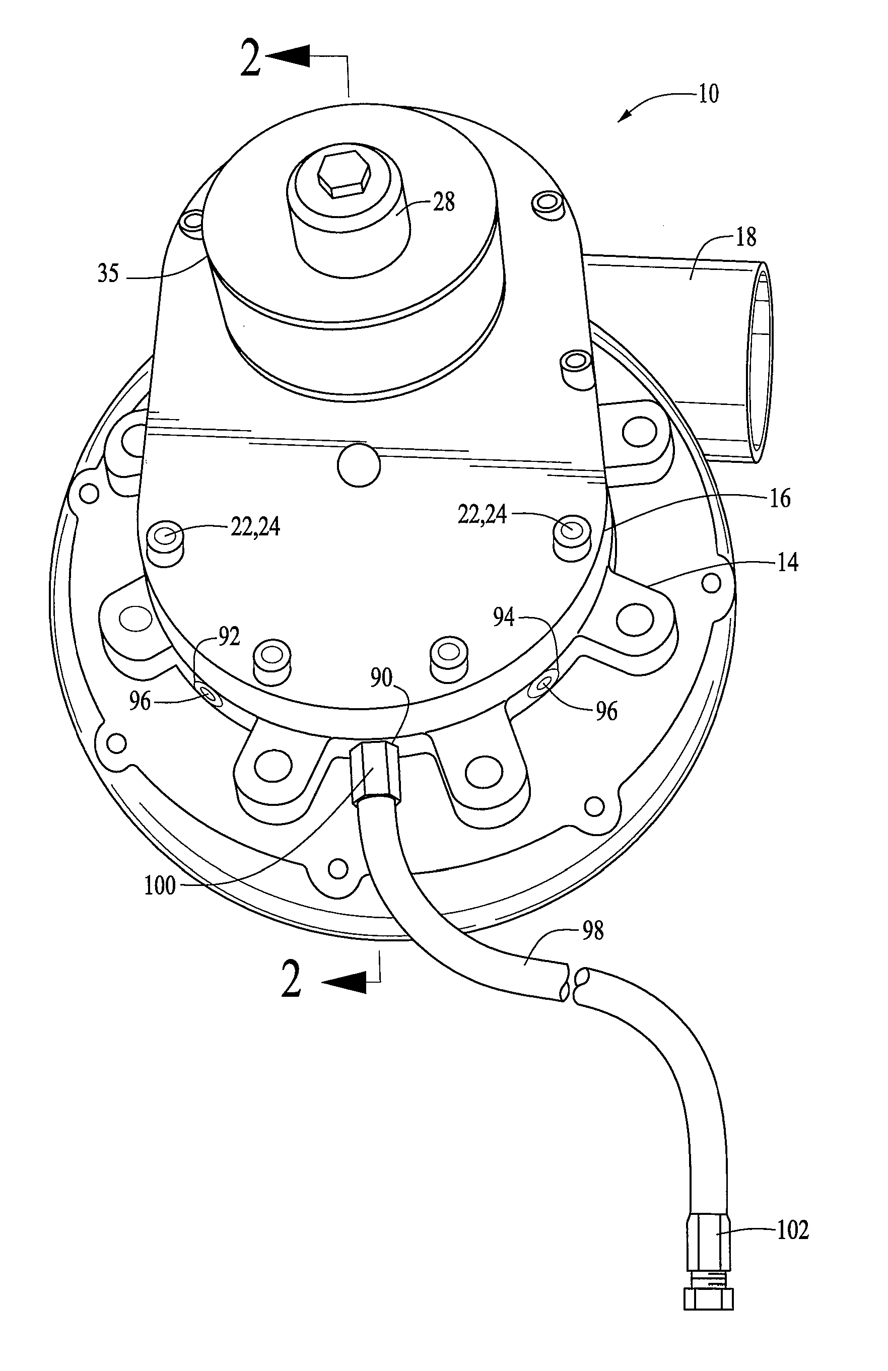
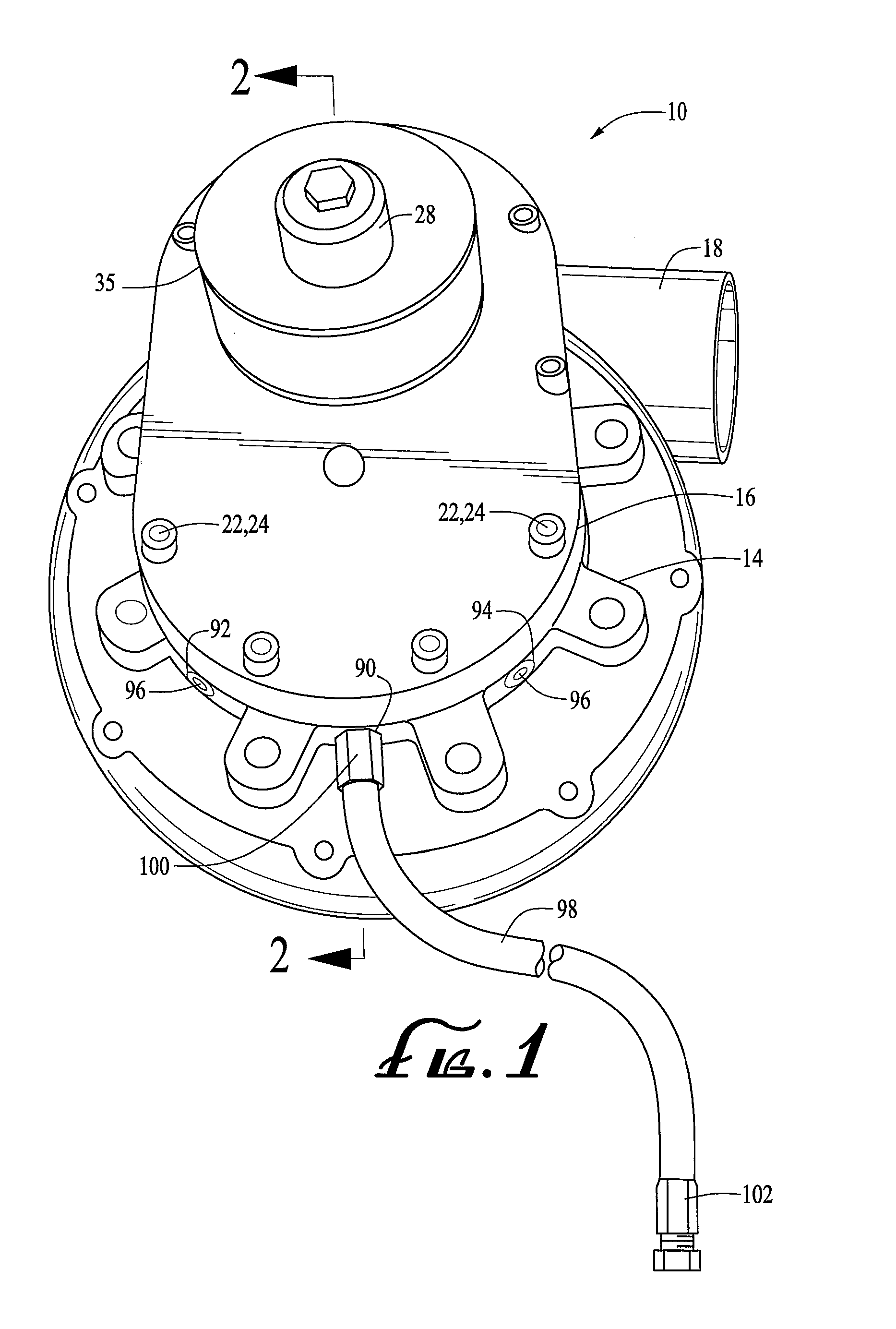
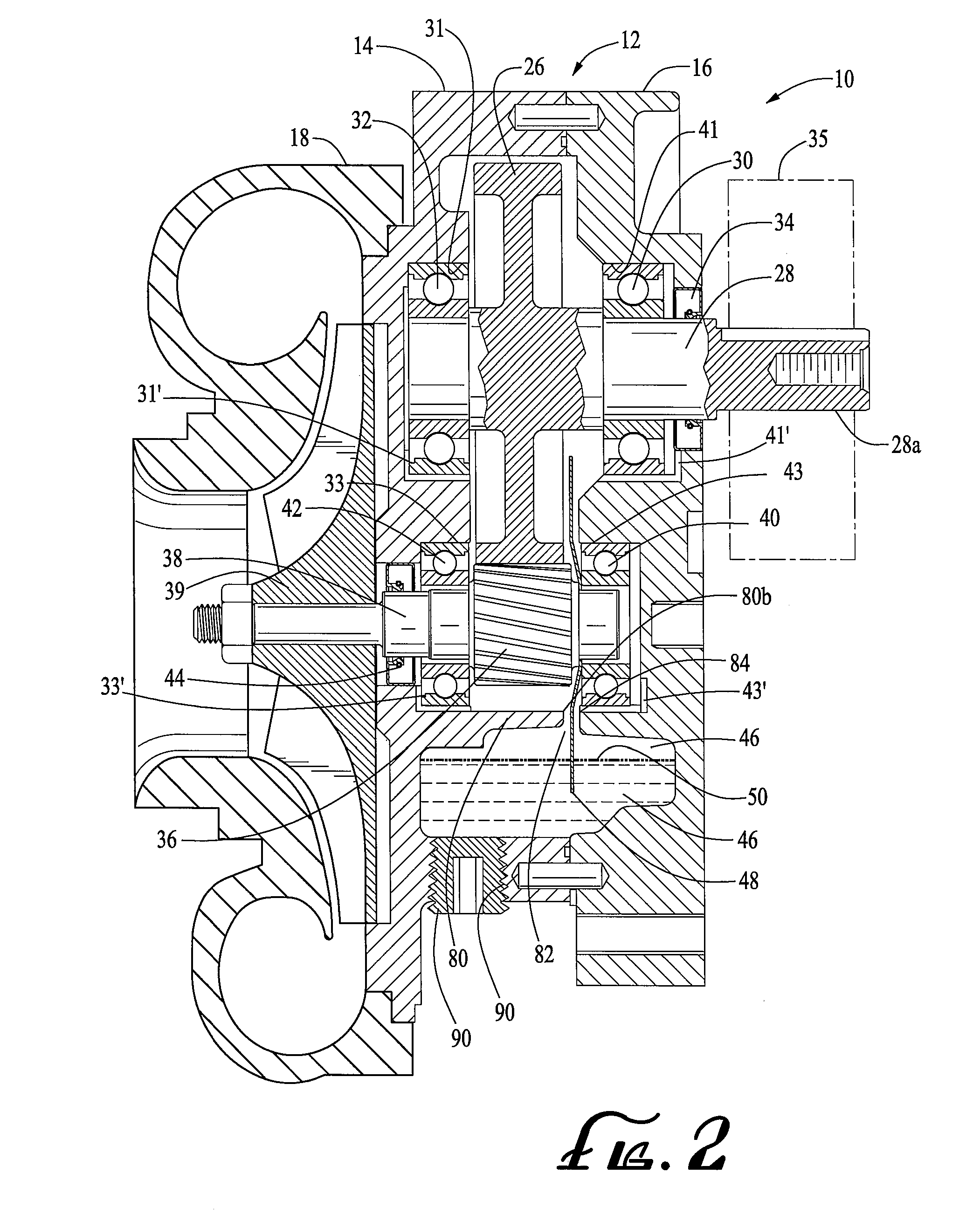
[0015]A preferred embodiment of the supercharger 10 of the present invention is a centrifugal supercharger of the type mechanically driven by an associated engine such as an internal combustion engine in an automobile. Such a supercharger is disclosed in Applicant's U.S. Pat. No. 5,224,459, the teachings of which are incorporated by reference as though fully set forth herein. In its preferred configuration, supercharger 10 of the present invention includes a housing 12 comprised of a gear case 14 and cover 16 and a volute 18, all of which are preferably aluminum castings. The volute is mounted onto the back plate 20 of the gear casing and the cover 16 is bolted onto the gear case 14 through a plurality of aligned apertures 22 and 24 in the case and cover. The large drive gear 26 is mounted on a drive shaft 28 which is supported by ball bearing assemblies 30 and 32 mounted in the aligned cylindrical bearing bores 31 and 41 in the gear case and cover, respectively. The drive shaft pro...


PUM


Abstract

A supercharger for an internal combustion engine having an internal reservoir adapted to receive a supply of lubricating oil. An oil slinger is mounted on the impeller shaft for rotation therewith that extends into the reservoir for collecting and slinging lubricating oil onto the supercharger bearings, shafts and the drive and impeller gears. A baffle assembly is carried by the interior of the supercharger housing for controlling the volume and flow of lubricating oil onto said gears and bearings and directing oil flow therefrom back into said reservoir to prevent excessive lubrication buildup on the gears and the deleterious effects that result therefrom.

Description

BACKGROUND OF THE INVENTION[0001]The present invention relates to superchargers for internal combustion engines and more particularly, to an improved, low cost and compact self-lubricating centrifugal supercharger employing a rotary driven oil slinger that avoids excessive lubrication disposition onto and around the shafts, gears and associated bearings and excessive lubrication build-up on the rapidly rotating gears that cause power losses and an undesirable rise in temperature of the lubrication oil.[0002]The use of oil slingers as an economical means of lubricating intermeshing gears and associated bearings has been well known for many years. See, for example, Gear Handbook, published in 1962 by McGraw-Hill Book Company. A gear or disc is mounted on a rotating shaft, typically a drive shaft, so as to pass a lower portion of the gear or disc through an internal reservoir of lubrication oil. As the rotating gear or disc passes through the reservoir of lubrication oil, it lubricates...

Claims


Application Information

Patent Timeline
Patent Type & Authority Applications(United States)
IPC IPC(8): F02B33/00
CPCF02B33/40F04D29/063F04D25/04F02B39/14
Inventor MIDDLEBROOK, JAMES K.REAGAN, MICHAEL W.SHEMENSKI, MATTHEW L.
Owner VORTECH ENG
Why Eureka
Try Eureka