Selective soldering bath

a soldering bath and selective technology, applied in the direction of soldering apparatus, manufacturing tools, auxillary welding devices, etc., can solve the problems of consuming around three square meters of valuable factory floor space, requiring the bulkiness of prior wave soldering machines to accommodate required soldering precision, etc., to facilitate safe loading and unloading of components, facilitate safe soldering, and facilitate safe loading and unloading of pwbs

Inactive Publication Date: 2010-01-07
SONY CORP +1
View PDF16 Cites 8 Cited by
  • Summary
  • Abstract
  • Description
  • Claims
  • Application Information

AI Technical Summary

Benefits of technology

[0005]A translational actuator may be provided to move the frame with carrier translationally in a horizontal plane to establish the second degree of freedom. The translational actuator can move the frame translationally in a horizontal plane between a load position, wherein the carrier is not over the solder bath to facilitate safe loading and unloading of components therefrom, and a solder position, wherein the carrier is over the bath to facilitate soldering. Furthermore, four ra...

Problems solved by technology

Furthermore, the bulkiness of the prior wave soldering machines has been necessitated to accommodate required sol...

Method used


Image

  • Selective soldering bath
  • Selective soldering bath
  • Selective soldering bath

Examples


Embodiment Construction

[0012]Terms of height such as “top”, “bottom”, “above”, “below”, “upper”, “lower”, “higher”, “lower”, etc. as used herein are relative to the soldering machine when it is positioned on the floor of an assembly plant as intended.

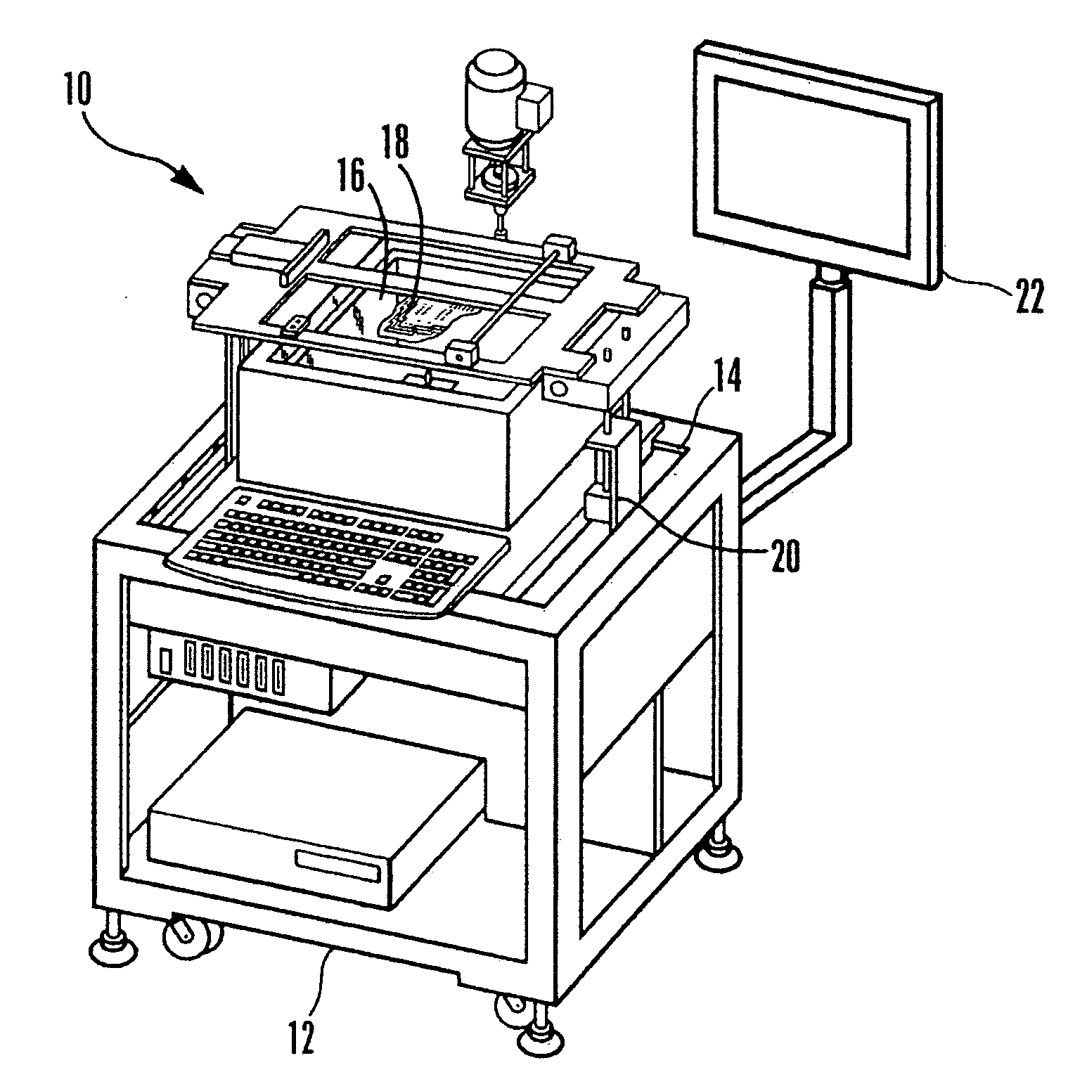
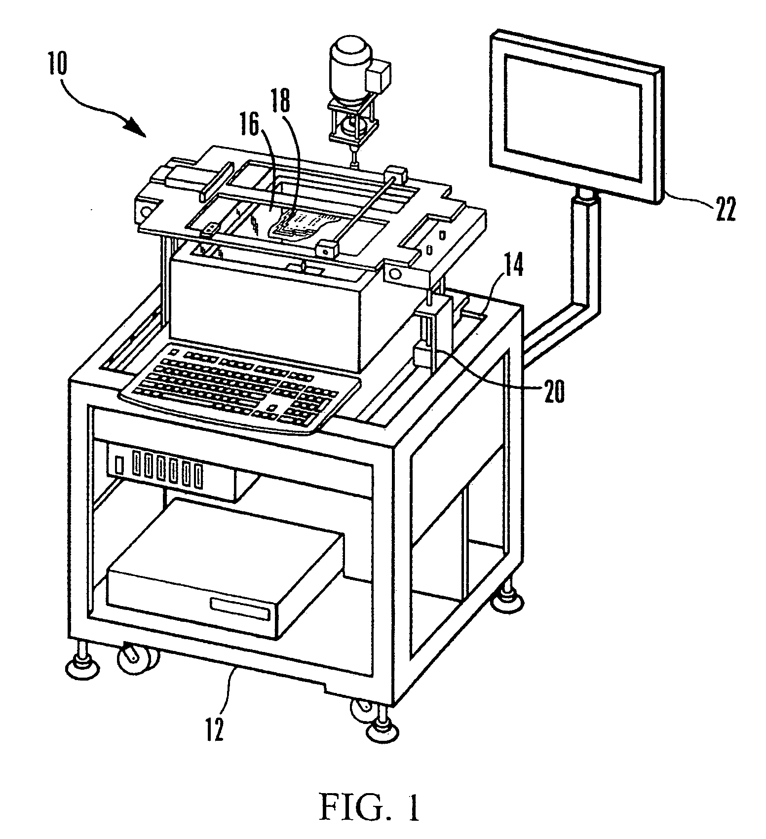
[0013]Referring initially to FIG. 1, a solder machine is shown, generally designated 10, which includes a shroud or housing 12 enclosing a frame 14 that is coupled to a solder bath 16 holding solder for dip-soldering components such as printed wiring boards (PWB) 18. The solder machine 10 may support a processor 20 (shown schematically in FIG. 1) that controls motion of the frame in accordance with disclosure below. The processor 20 may output information on a computer monitor 22 if desired.

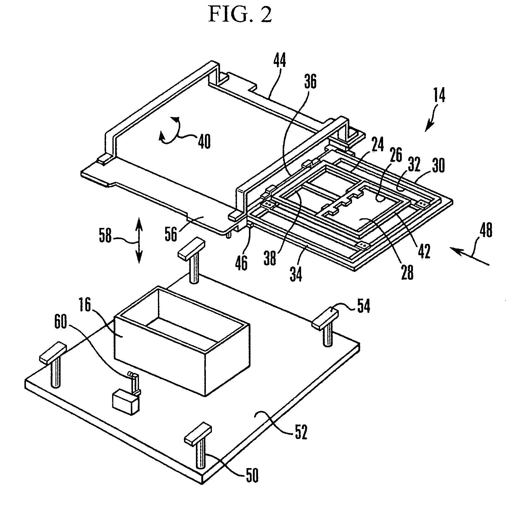
[0014]Details of the frame 14 and how it moves with three degrees of freedom relative to the (non-moving) solder bath 16 can be seen in cross-reference to FIG. 2. The frame 14 includes a top flat generally rectilinear PWB carrier 24 which includes support structure 26 for ...


PUM

PropertyMeasurementUnit
Angleaaaaaaaaaa
Degree of freedomaaaaaaaaaa

Abstract

A solder machine uses various linear actuators to move a PWB carrier in three degrees of freedom relative to a solder bath, to facilitate safe loading and unloading of PWBs onto the carrier while the carrier is distanced from the bath, and then to move the carrier over the bath, lower it, and tilt it as necessary to effect soldering.

Description

FIELD OF THE INVENTION[0001]The present invention relates generally to printed wiring board (PWB) soldering machines that dip, in two degrees of freedom, PWBs into a solder bath to effect soldering.BACKGROUND OF THE INVENTION[0002]Solder machines are used to dip components such as printed wiring boards into solder baths to effect mechanical-electrical connections. To undertake this dipping automatically, previous wave soldering systems have been used that have been relatively bulky to accommodate necessary conveyance of the PWBs into the solder bath at the desired locations of the PWBs. Furthermore, the bulkiness of the prior wave soldering machines has been necessitated to accommodate required soldering precision. Such prior machines have typically consumed around three square meters of valuable factory floor space.SUMMARY OF THE INVENTION[0003]A solder machine includes a solder bath and a frame juxtaposed with the solder bath and including a carrier configured for holding at least...

Claims


Application Information

Patent Timeline
IPC IPC(8): B23K1/20B23K37/047
CPCB23K3/0676B23K1/08
Inventor ALVAREZ SERRANO, ESTEBAN ARTUROMILLAN SANCHEZ, HORMAN ARMANDO
Owner SONY CORP
Why Eureka
Try Eureka