System and Method for Driving LED with High Efficiency in Power Consumption

a technology of power consumption and leds, applied in the direction of instruments, process and machine control, light sources, etc., can solve the problems of associated illuminance, disadvantageous consumption of precious power, etc., and achieve the effect of constant current and illuminance, and increasing efficiency in power consumption

Active Publication Date: 2010-01-07
HIMAX DISPLAY INC
View PDF4 Cites 25 Cited by
  • Summary
  • Abstract
  • Description
  • Claims
  • Application Information

AI Technical Summary

Benefits of technology

[0008]In view of the foregoing, it is an object of the present invention to provide system and method for driving the LED with constant current and illuminance, and with increased efficiency in power consumption.
[0009]According to the embodiment, the driving system includes a constant-current mode circuit for providing a constant current to the LED, and a constant-voltage mode circuit for providing a constant voltage to the LED. A switch is utilized to switch between the constant-current mode circuit and the constant-voltage mode circuit to assert constant-current mode and constant-voltage mode respectively. Accordingly, the forward voltage of the LED could be maintained constant, and the efficiency in power consumption could be substantially increased.

Problems solved by technology

Consequently, the LED suffers varying driving current, and thus its associated illuminance.
Furthermore, the LED in the conventional constant-voltage driving method is typically connected in series with a current-limiting resistor, which disadvantageously consumes precious power.
Although the LED driving current (and its associated illuminance) in the conventional constant-current method does not vary with respect to the fluctuating forward voltage VF, the LED, however, is connected in series with a current-sensing resistor, which disadvantageously consumes precious power.

Method used


Image

  • System and Method for Driving LED with High Efficiency in Power Consumption
  • System and Method for Driving LED with High Efficiency in Power Consumption
  • System and Method for Driving LED with High Efficiency in Power Consumption

Examples


Embodiment Construction

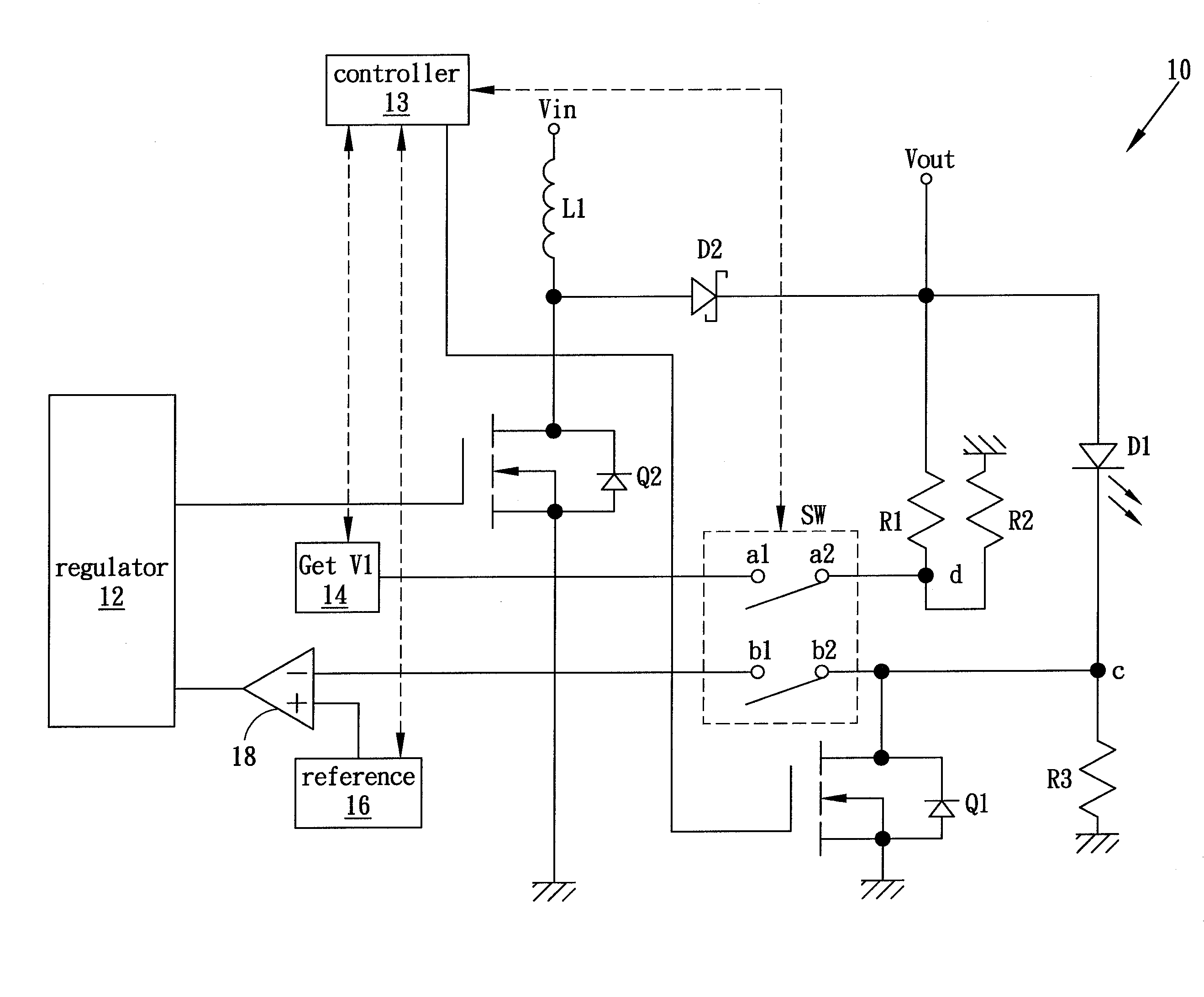
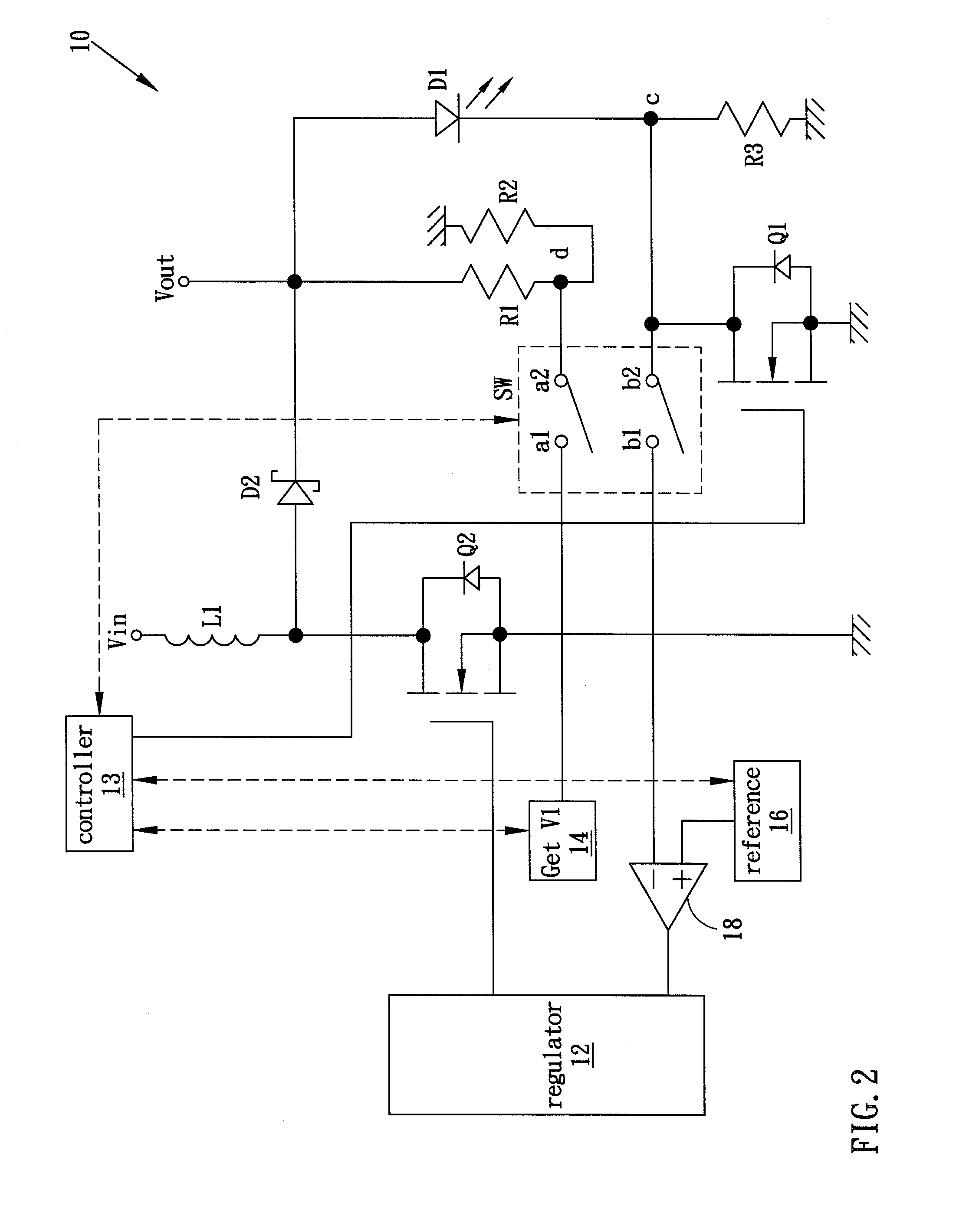
[0016]FIG. 2 illustrates a LED driving system 10 according to one embodiment of the present invention. Although one LED is demonstrated in the embodiment, a person skilled in the pertinent art will appreciate that more than one LED may be adapted, and the LEDs may be connected in either series or parallel. In the embodiment, a regulator 12 continuously switches the transistor Q2 on and off in turn such that the supply voltage Vin stores energy in the inductor L1 when the transistor Q2 is turned on, and the stored energy is delivered to the LED D1 at the output node Vout when the transistor Q2 is turned off. The rectifying diode D2 is used to prevent the current from being returned from the output node Vout back to the supply voltage Vin. The switching duty cycle of the regulator 12 varies according to the output of an error comparator 18. For example, the switching duty cycle increases when the output of the error comparator 18 increases, indicating that the LED output voltage or cu...


PUM


Abstract

A system and method for driving a LED is disclosed. The system is switched in turn between a constant-current mode circuit and a constant-voltage mode circuit. Accordingly, the forward voltage of the LED could be maintained constant, and the efficiency in power consumption could be substantially increased.

Description

BACKGROUND OF THE INVENTION[0001]1. Field of the Invention[0002]The present invention generally relates to driving light-emitting diode (LED), and more particularly to system and method for driving the LED with high efficiency in power consumption.[0003]2. Description of the Prior Art[0004]The light-emitting diode (LED) is widely used in a variety of electronic devices for diverse purposes. For example, the LEDs may be utilized in the backlight module of a liquid crystal display (LCD) to provide backlight, or may provide flash light in a charge-couple device (CCD) camera. In practice, the LED is, however, temperature dependent, or, in other words, the characteristics of the LED vary according to its temperature. FIG. 1 shows an LED and its equivalent circuit. The LED is equivalently made of a voltage source connected in series with a negative-temperature-coefficient (NTC) resistor. The resistance of the NTC resistor falls with increasing temperature caused by the current flowing thr...

Claims


Application Information

Patent Timeline
Patent Type & Authority Applications(United States)
IPC IPC(8): G05F1/10
CPCH05B33/0824H05B33/0815H05B45/3725H05B45/44
Inventor CHEN, CHIN-ZUNG
Owner HIMAX DISPLAY INC
Why Eureka
Try Eureka