High efficiency modulating RF amplifier

a high-efficiency, rf amplifier technology, applied in the direction of amplifiers with field-effect devices, reconfigurable analogue/digital converters, code conversion, etc., can solve the problem of insufficient bandwidth of state of the art switched mode power supplies, complexity of power envelope modulation on the magnitude driver, and insufficient efficiency enhancement. to meet bandwidth requirements, the effect of high-efficiency modulating r

Inactive Publication Date: 2010-01-07
KONINKLIJKE PHILIPS ELECTRONICS NV
View PDF9 Cites 73 Cited by
  • Summary
  • Abstract
  • Description
  • Claims
  • Application Information

AI Technical Summary

Benefits of technology

[0006]It is an object of the invention to provide a high e

Problems solved by technology

It is a disadvantage that the incorporation of the power envelope modulation on the magnitude driver complicates the design since both the switched mode regulator and the linear modulator must be made responsive to the magnitude signal.
It is a further disadvantage that despite the more complicated design the efficiency enhanceme

Method used


Image

  • High efficiency modulating RF amplifier
  • High efficiency modulating RF amplifier
  • High efficiency modulating RF amplifier

Examples


Embodiment Construction

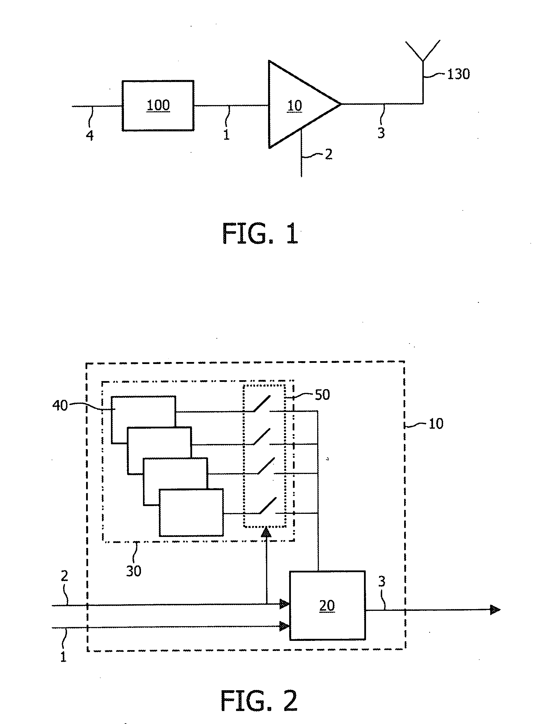
[0027]There are several known architectures for the transmission of signals, one of them being polar transmission. With polar transmission a signal to be transmitted is represented in the form of polar signals being an envelope signal r(t) 2 and a phase information signal phi(t) 1. The envelope signal r(t0) provides an instantaneous amplitude at t=t0, and the phase information signal phi(t0) gives an instantaneous phase at t=t0. The transmitted signal may be written as

s(t)=r(t)*Re(ej[ω0t+phi(t)])

[0028]FIG. 1 shows a simplified schematic diagram of the polar transmitter architecture. The polar transmitter architecture comprises a Voltage Controlled Oscillator and / or Phase Locked Loop 100 and a modulating RF amplifier 10. By modulation of a phase signal 4 provided to the Voltage Controlled Oscillator and / or Phase Locked Loop 100 the phase information signal phi(t) 1 is obtained and coupled to an input of the modulating RF amplifier 10. The envelope signal r(t) 2 is coupled to a furthe...


PUM


Abstract

A high efficiency modulating RF amplifier (10) for amplitude modulating a signal defined by a phase information signal (1) and an envelope signal (2) comprises a power supply (30) arranged to provide an operating voltage under control of the envelope signal (2). The power supply (30) comprises a plurality of power supply stages (40) and a plurality of supply switches (50) coupled between the plurality of power supply stages (40) and the modulator (20). The power supply (30) is arranged to select one of the power supply stages (40) to provide the operating voltage under control of the envelope signal (2). The high efficiency modulator RF amplifier further comprises a modulator (20) for receiving the phase information signal (1), the envelope signal (2) and the operating voltage. The modulator (20) is arranged to provide an output signal of which an amplitude is modulated under control of the envelope signal (2).

Description

FIELD OF THE INVENTION[0001]The invention relates to a high efficiency modulating RF amplifier for amplitude modulating a signal. The invention further relates to a polar transmitter comprising a high efficiency modulating RF amplifier and to a device comprising a polar transmitter.[0002]Examples of such a device are mobile phones and wireless interfaces.BACKGROUND OF THE INVENTION[0003]U.S. Pat. No. 6,816,016 discloses a polar transmitter using a high efficiency modulating RF amplifier. The high efficiency modulating RF amplifier comprises an amplifier supplied by a magnitude driver controlling the output power of the amplifier. A data signal is applied to a modulation encoder that produces magnitude and phase signals. The magnitude signal is applied to the magnitude driver, and the magnitude driver provides an operating voltage for the amplifier. The magnitude driver also receives a power control signal. In response, the magnitude driver produces an operating voltage that is appli...

Claims


Application Information

Patent Timeline
IPC IPC(8): H03F3/16
CPCH03F1/0227H03M1/745H03M1/004
Inventor VAN ZEIJL, PAULUS THOMAS MARIACOLLADOS ASENSIO, MANEL
Owner KONINKLIJKE PHILIPS ELECTRONICS NV
Why Eureka
Try Eureka