Planar dielectric waveguide with metal grid for antenna applications

Active Publication Date: 2010-01-07
SIERRA NEVADA CORP
View PDF12 Cites 34 Cited by
  • Summary
  • Abstract
  • Description
  • Claims
  • Application Information

AI Technical Summary

Benefits of technology

[0010]As will be more readily appreciated from the detailed description that follows, the present disclosure provides a waveguide that permits transmission or reception of electromagneti

Problems solved by technology

When multiple, steerable or beam steering antennas are used in close proximity, the waveguide described above may obstru

Method used


Image

  • Planar dielectric waveguide with metal grid for antenna applications
  • Planar dielectric waveguide with metal grid for antenna applications
  • Planar dielectric waveguide with metal grid for antenna applications

Examples


Embodiment Construction

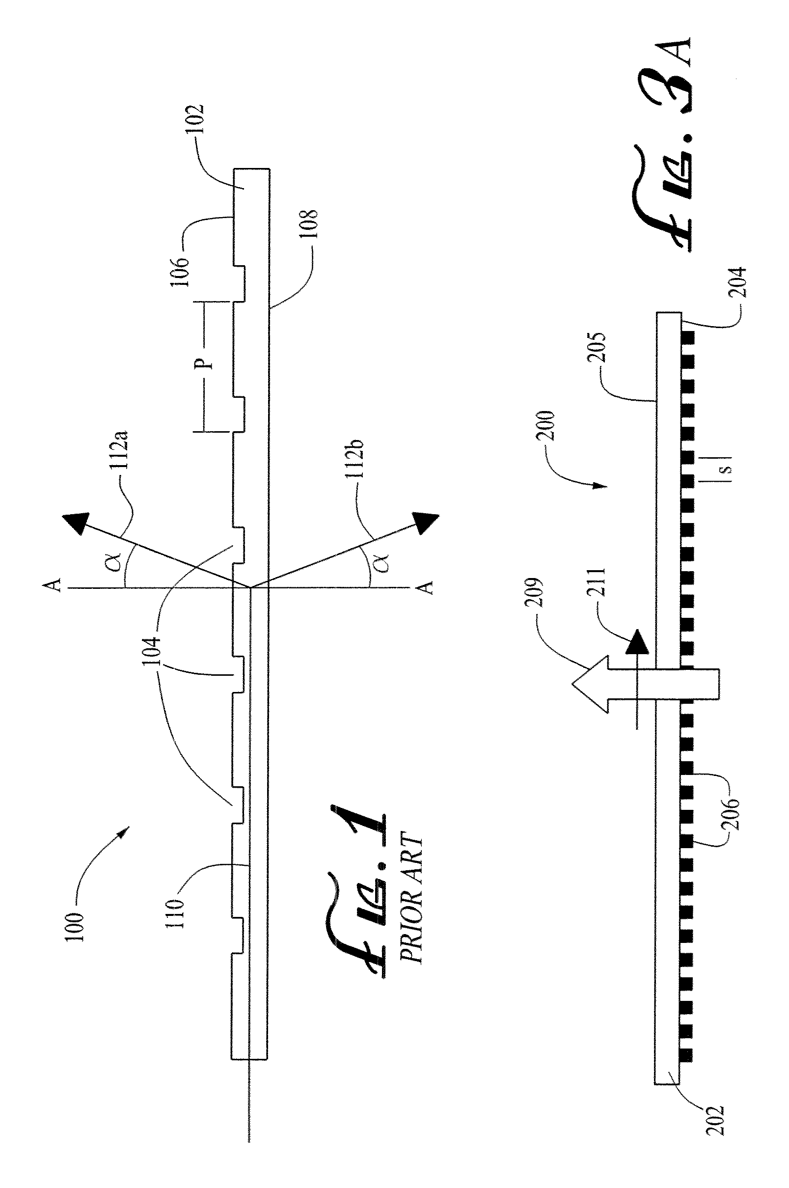
[0019]FIG. 1 illustrates a leaky waveguide antenna 100, of a conventional type well known in the art. The leaky waveguide antenna 100 includes a dielectric substrate or slab 102, with a top surface 106 and bottom surface 108. A diffraction grating comprising a plurality of diffraction grating scattering elements 104 is provided on the top surface 106 of the dielectric slab 102. A longitudinal electromagnetic wave propagates through the dielectric slab 102, between the top surface 106 and bottom surface 108, along a longitudinal propagation path 110. Based upon the characteristics of the leaky waveguide antenna 100, the longitudinal wave is diffracted and radiates out of the dielectric slab 102 in two directions, along a first or forward diffracted path 112a and a second or backward diffracted path 112b, at a beam angle α, measured with reference to a line A-A perpendicular to the propagation path 110, prior to the radiation. The beam angle α is given by the formula: sin α=β / k−λ / P, w...


PUM


Abstract

A waveguide includes a dielectric substrate having first and second opposed surfaces defining a longitudinal wave propagation path therebetween; and a conductive grid on the first surface of the substrate and comprising a plurality of substantially parallel metal strips, each defining an axis. The grid renders the first surface of the substrate opaque to a longitudinal electromagnetic wave propagating along the longitudinal wave propagation path and polarized in a direction substantially parallel to the axes of the strips. The grid allows the first surface of the substrate to be transparent to a transverse electromagnetic wave having a transverse propagation path that intersects the first and second surfaces of the substrate and having a polarization in a direction substantially normal to the plurality of metal strips. A diffraction grating on the second surface allows the waveguide to function as an antenna element that may be employed in a beam-steering antenna system.

Description

CROSS-REFERENCE TO RELATED APPLICATION[0001]Not ApplicableFEDERALLY SPONSORED RESEARCH OR DEVELOPMENT[0002]Not ApplicableBACKGROUND OF THE INVENTION[0003]The present disclosure relates generally to the field of waveguides that permit transmission or reception of electromagnetic radiation (particularly millimeter wavelength radiation) with certain characteristics in selective directions while not substantially impacting the transmission and reception of electromagnetic radiation with different characteristics. This disclosure further relates to the use of such waveguides in antenna applications.[0004]Dielectric waveguide antennas are well-known in the art, as exemplified by U.S. Pat. No. 6,750,827; U.S. Pat. No. 6,211,836; U.S. Pat. No. 5,815,124; and U.S. Pat. No. 5,959,589, the disclosures of which are incorporated herein by reference. Such antennas operate by the evanescent coupling of electromagnetic waves out of an elongate (typically rod-like) dielectric waveguide to a rotating...

Claims


Application Information

Patent Timeline
IPC IPC(8): H01Q13/00H01Q13/20H01Q3/00
CPCH01Q13/28H01Q3/20
Inventor MANASSON, VLADIMIRKHODOS, VICTORSADOVNIK, LEVAVAKIAN, ARAMAISLITVINOV, VLADIMIRJIA, DEXINFELMAN, MIKHAILARETSKIN, MARK
Owner SIERRA NEVADA CORP
Why Eureka
Try Eureka