Proximity sensor switch-controlled meter and lamp switch system

Inactive Publication Date: 2010-01-07
SU KUO HSIN +1
View PDF20 Cites 50 Cited by
  • Summary
  • Abstract
  • Description
  • Claims
  • Application Information

AI Technical Summary

Benefits of technology

[0008]It is one object of the present invention to provide a proximity sensor switch-controlled meter and lamp switch system for motor vehicle, which uses

Problems solved by technology

The aforesaid meter and lamp switching arrangement has drawbacks as follows:1. External moisture and dust may enter the inside of the electronic meter through the through holes on the transparent glass and the through holes on the faceplate to contaminate or wet the precision electronic components of the electronic meter when t

Method used


Image

  • Proximity sensor switch-controlled meter and lamp switch system
  • Proximity sensor switch-controlled meter and lamp switch system
  • Proximity sensor switch-controlled meter and lamp switch system

Examples


Example

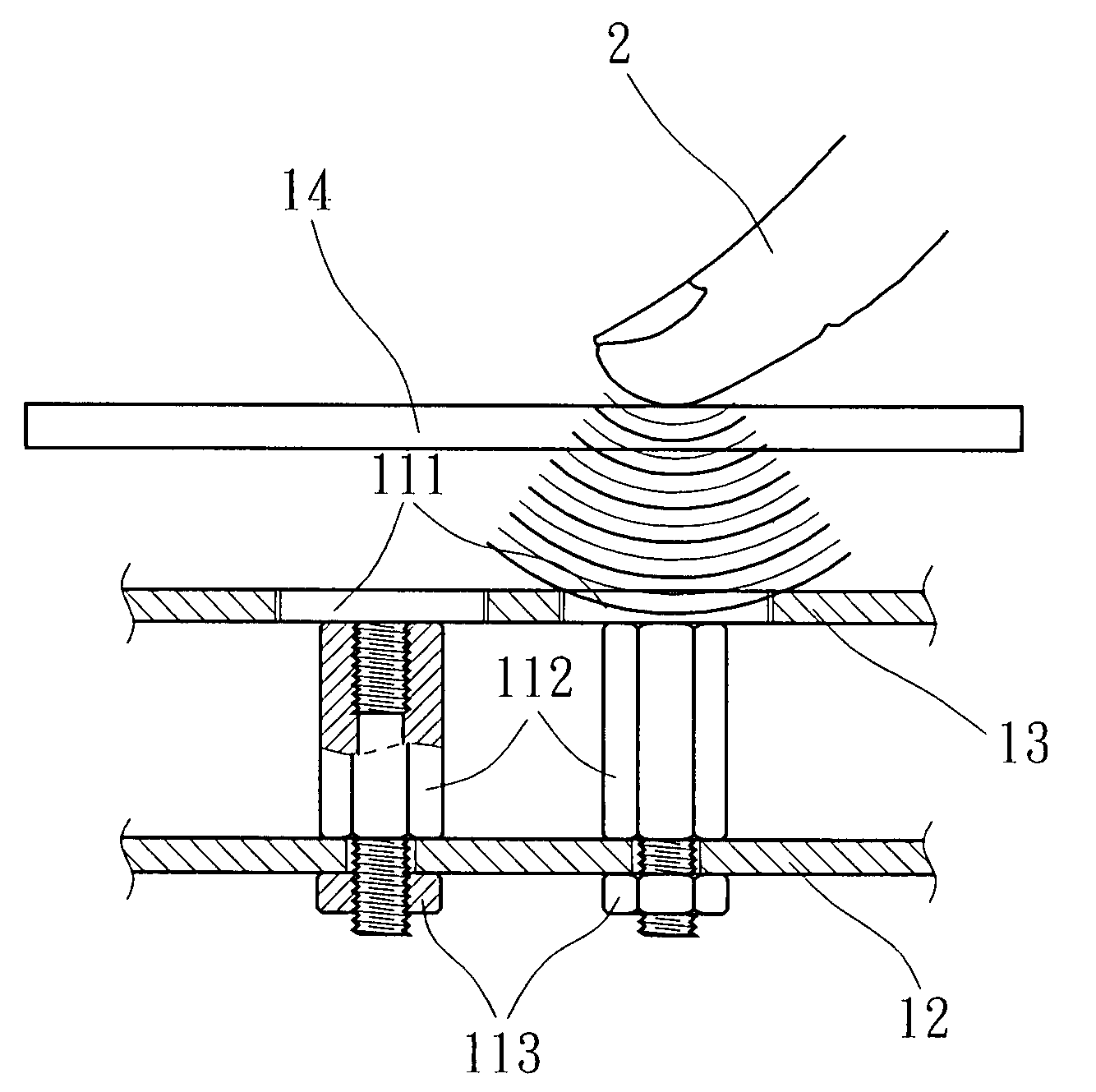
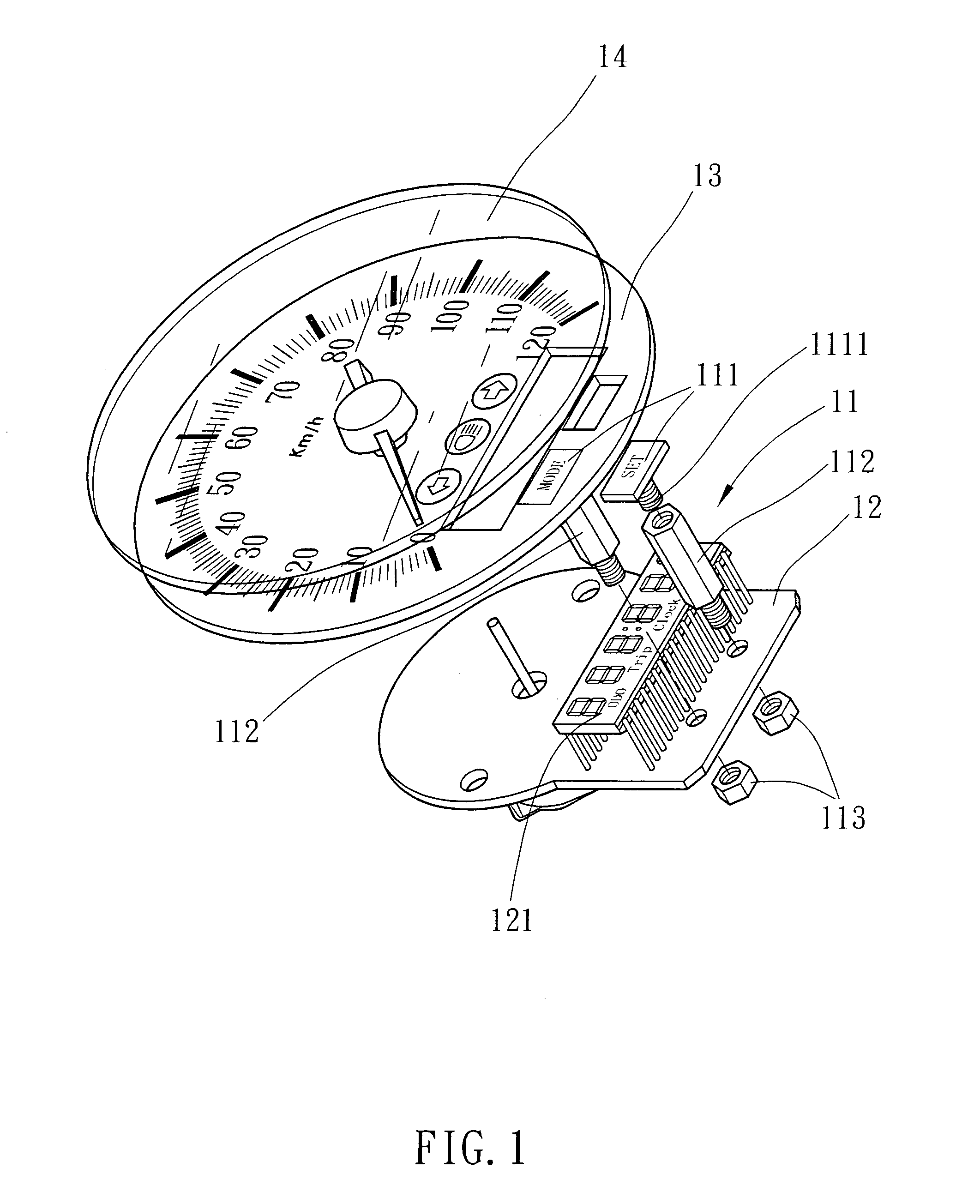
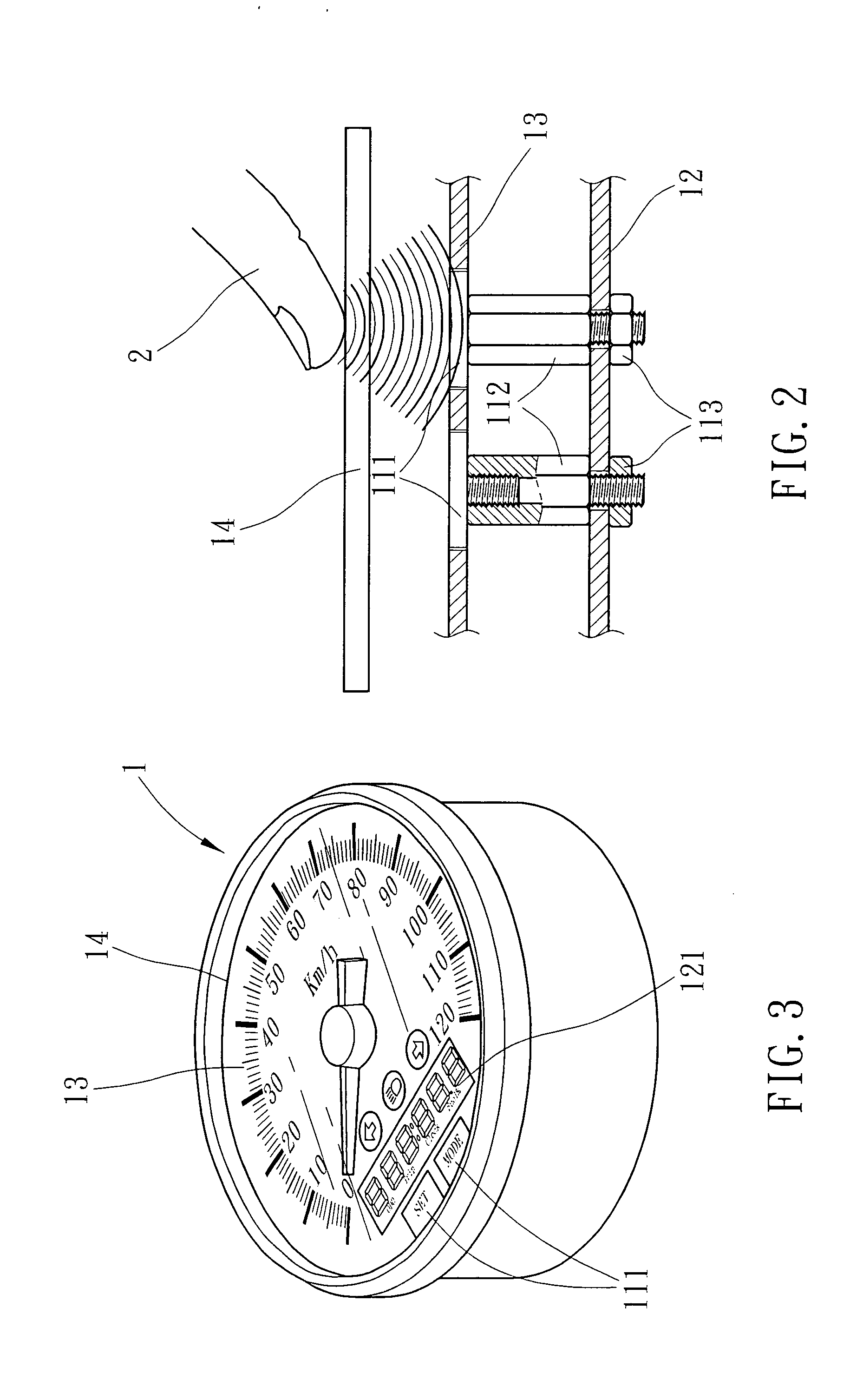
[0026]Referring to FIGS. 1˜4, a proximity sensor switch-controlled meter and lamp switch system is used in a vehicle (car or motorcycle), comprising an electronic meter 1 and a lamp switch system controllable by a touch of a human finger 2 to switch the display information of the electronic meter 1 or to turn on / off the headlamp 127 and / or the left or right turn signal light 128. The electronic meter 1 comprises a faceplate 13, a transparent glass 14 covering the faceplate 13, a circuit board 12 disposed at the bottom side of the faceplate 13, and a plurality of proximity sensor switches 11 installed in the faceplate 13 and the circuit board 12 for setting and display mode control. Each proximity sensor switch 11 comprises an induction plate 111 mounted in the faceplate 13 and having a bottom conductor 1111, a conducting member, which can be a wire conductor, metal conducting column, non-metallic conducting member or printed circuit board and which, according to the present preferre...


PUM


Abstract

A proximity sensor switch-controlled meter and lamp switch system installed in a motor vehicle that can be a motorcycle or car is disclosed to include a meter having a micro-controller unit (MCU) and an electronic display device, a lamp switch unit installed in one handlebar (or the motorcycle) or steering wheel (of the car), and proximity sensor switches respectively mounted in the meter and the lamp switch unit for controlling the micro-controller unit (MCU) to control the display mode of an electronic display device of the meter or to switch on/off the headlamp or left/right turn signal light of the motor vehicle when the motorcycle rider or car driver touches the meter or the lamp switch unit with a finger.

Description

BACKGROUND OF THE INVENTION[0001]1. Field of the Invention[0002]The present invention relates to a display control of an electronic meter of a motor vehicle and on / off switching control of the headlamp and left / right turn signal lights of the motor vehicle and, more particularly, to a proximity sensor switch-controlled meter and lamp switch system for motor vehicle.[0003]2. Description of the Related Art[0004]A conventional vehicle electronic meter 5, as shown in FIGS. 9˜12, comprises a circuit board 52 carrying a plurality of switches 522 and a microprocessor 523, a transparent glass 54 having a recessed portion 541 and a plurality of through holes 542 cut through the recessed portion 541, a combination of rubber key caps 51 mounted in the recessed portion 541 and packed with a packing frame 512, a faceplate 53 set between the transparent glass 54 and the circuit board 52 and having a plurality of through holes 531 in alignment between the through holes 542 of the transparent glass...

Claims


Application Information

Patent Timeline
IPC IPC(8): G06F3/045G06F3/041
CPCB60Q1/0082H03K2217/960755H03K17/9622B60Q1/1484
Inventor SU, KUO-HSINCHANG, I-TE
Owner SU KUO HSIN
Why Eureka
Try Eureka