Image pickup apparatus, method of controlling the same, and storage medium

a pickup apparatus and image technology, applied in the direction of printers, instruments, camera focusing arrangement, etc., can solve the problems of discomfort of photographers, inability to obtain inability to achieve the in-focus position of the focus lens, etc., to achieve high speed

Inactive Publication Date: 2010-01-07
CANON KK
View PDF15 Cites 17 Cited by
  • Summary
  • Abstract
  • Description
  • Claims
  • Application Information

AI Technical Summary

Benefits of technology

[0016]The present invention provides an image pickup apparatus which is capable of performing stable focusing on an object intended by a photographer, at high ...

Problems solved by technology

However, when an object is moving or when a camera shake by a photographer has occurred, it is not always possible to obtain an in-focus position of a focus lens for the face detection area by the phase difference detection method.
This makes a photographer feel uncomfortable.
Further, when the external phase difference detection method is employed, an optical system different from the main optical system of the photographic lens is used, which causes a parallax.
In this case, it is judged that image blur has occurred, and the backgro...

Method used


Image

  • Image pickup apparatus, method of controlling the same, and storage medium
  • Image pickup apparatus, method of controlling the same, and storage medium
  • Image pickup apparatus, method of controlling the same, and storage medium

Examples


first embodiment

[0040]First, a description will be given of an image pickup apparatus according to the present invention. Although in the present embodiment, the image pickup apparatus is a video camera, this is not limitative, but another type of image pickup apparatus, such as a digital still camera, may be employed.

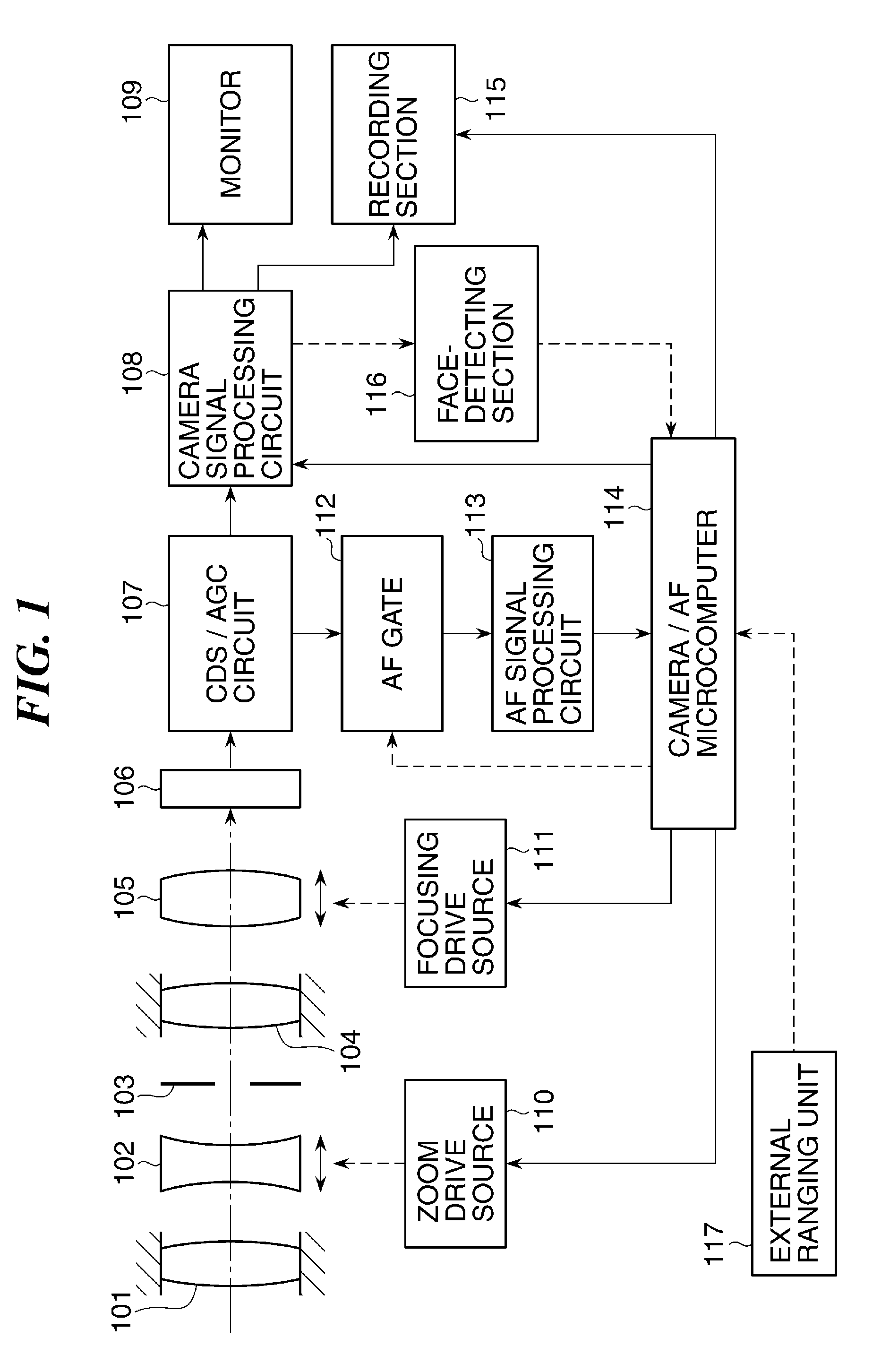
[0041]FIG. 1 is a block diagram of a main part of the video camera as the image pickup apparatus according to the present embodiment.

[0042]Referring to FIG. 1, reference numeral 101 denotes a first fixed lens group; reference numeral 102, a variable power lens that performs a variable power or zooming operation while moving in an optical axis direction to vary a focal length; and reference numeral 103, a diaphragm. Further, reference numeral 104 denotes a second fixed lens group; and reference numeral 105, a focus compensator lens (hereinafter simply referred to as “the focus lens”) equipped with both a function of correcting deviation of a focal plane due to a variable power operatio...

second embodiment

[0165]Next, a description will be given of an image pickup apparatus according to the present invention.

[0166]The image pickup apparatus according to the present embodiment is distinguished from the image pickup apparatus according to the above-described first embodiment in which the external phase difference detection (external ranging) method is used, only in that the TTL (internal ranging) phase difference detection method is employed. Therefore, duplicate description of the construction and effects is omitted, and only different points of the construction and effects of the present embodiment from those of the first embodiment will be described hereafter.

[0167]FIG. 14 is a block diagram of essential parts of a video camera as the image pickup apparatus according to the present embodiment.

[0168]As shown in FIG. 14, the video camera has a photographic optical system comprised of a first fixed lens group 101, a variable power lens 102, a focus lens 105, a diaphragm 103, and a secon...


PUM


Abstract

An image pickup apparatus which is capable of performing stable and high-speed focusing on an object intended by a photographer. In a video camera as the image pickup apparatus, an image pickup element picks up an object image formed by a photographic optical system including a focus lens and thereby outputs a video signal. A face-detecting section detects a face detection area based on the video signal. An AF signal processing circuit generates an AF evaluation value signal. An external ranging unit generates object distance information. A microcomputer performs a TV-AF process using an AF evaluation value of the AF evaluation value signal and an external ranging AF process using the object distance information. The microcomputer controls execution of the two focus control processes according to a result of the detection by the face-detecting section.

Description

BACKGROUND OF THE INVENTION[0001]1. Field of the Invention[0002]The present invention relates to an image pickup apparatus, a method of controlling the same, and a storage medium, and more particularly to an image pickup apparatus configured to detect an object area in an image pickup screen and perform focus control based on a result of the detection.[0003]2. Description of the Related Art[0004]In the autofocus (AF) control of an image pickup apparatus, such as a video camera, a TV-AF method is predominant in which an AF evaluation value signal is generated that is indicative of the sharpness (contrast state) of a video signal generated using an image pickup element, and a focus lens position that is searched for that represents where the AF evaluation value signal assumes a maximum value.[0005]Further, there has been known an image pickup apparatus having a human face detecting function so as to stably focus on a human object in the case of photographing a human being. For example...

Claims


Application Information

Patent Timeline
IPC IPC(8): H04N5/232G06K9/46
CPCG03B3/00H04N5/23219H04N5/23212G03B13/36H04N23/673H04N23/675H04N23/61H04N23/611
Inventor ISHII, KAZUNORI
Owner CANON KK
Why Eureka
Try Eureka