Image displaying device and method,and image processing device and method

Active Publication Date: 2010-01-07
SHARP KK
View PDF16 Cites 25 Cited by
  • Summary
  • Abstract
  • Description
  • Claims
  • Application Information

AI Technical Summary

Benefits of technology

[0079]According to the present invention, the image quality deterioration of displayed images may effectively be prevented by not executing the interpolation

Problems solved by technology

As compared to conventional cathode-ray tubes (CRTs) primarily used for realizing moving images, LCDs (Liquid Crystal Displays) have a drawback, so-called motion blur, which is the blurring of outline of a moving portion perceived by a viewer when displaying a moving image.
Since the impulse response of the image displaying light has a temporal spread in the above hold display mode, spatial frequency characteristics deteriorate along with temporal frequency characteristics, resulting in the motion blur.
Since the human eye can smoothly follow a moving object, if the light emission time is long as in the case of the hold type, the movement of image seems jerky and unnatural due to the time integration effect.
However, in the case of the frame interpolation processing using the linear interpolation, unnaturalness of motion (jerkiness, judder) is generated due to the frame rate conversion, and the motion blur disturbance due to the above hold display mode cannot sufficiently be improved, resulting in inadequate image quality.
Incidentally, when the FRC is considered to be realized by a real-time processing of a hardware or a simulation processing of a computer, etc., the calculation range for evaluating motion vectors needs to be limited in real use because of limitation to the circuit configuration or memory region of the hardware, or limitation to computer processing speed, etc.
However, when the movement amount between frames is large, the vector acquired by

Method used


Image

  • Image displaying device and method,and image processing device and method
  • Image displaying device and method,and image processing device and method
  • Image displaying device and method,and image processing device and method

Examples


Example

[0125]In a first embodiment of the present invention, when the movement amount between the frames of the input image signal is larger than a predetermined value, the output of the motion vector detecting portion 11e is forced to be zero-vector to make the motion compensation processing of the FRC portion 10 ineffective.

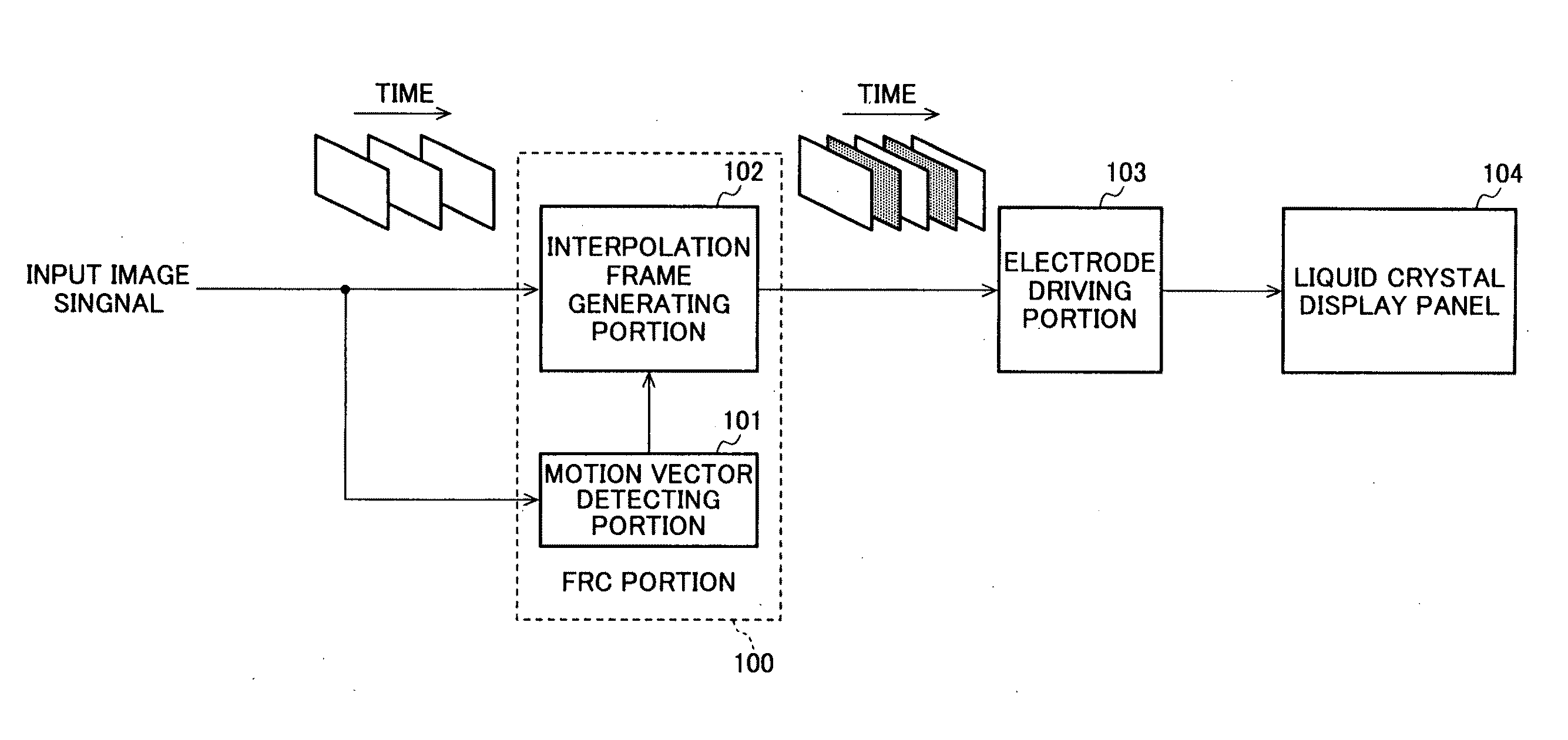
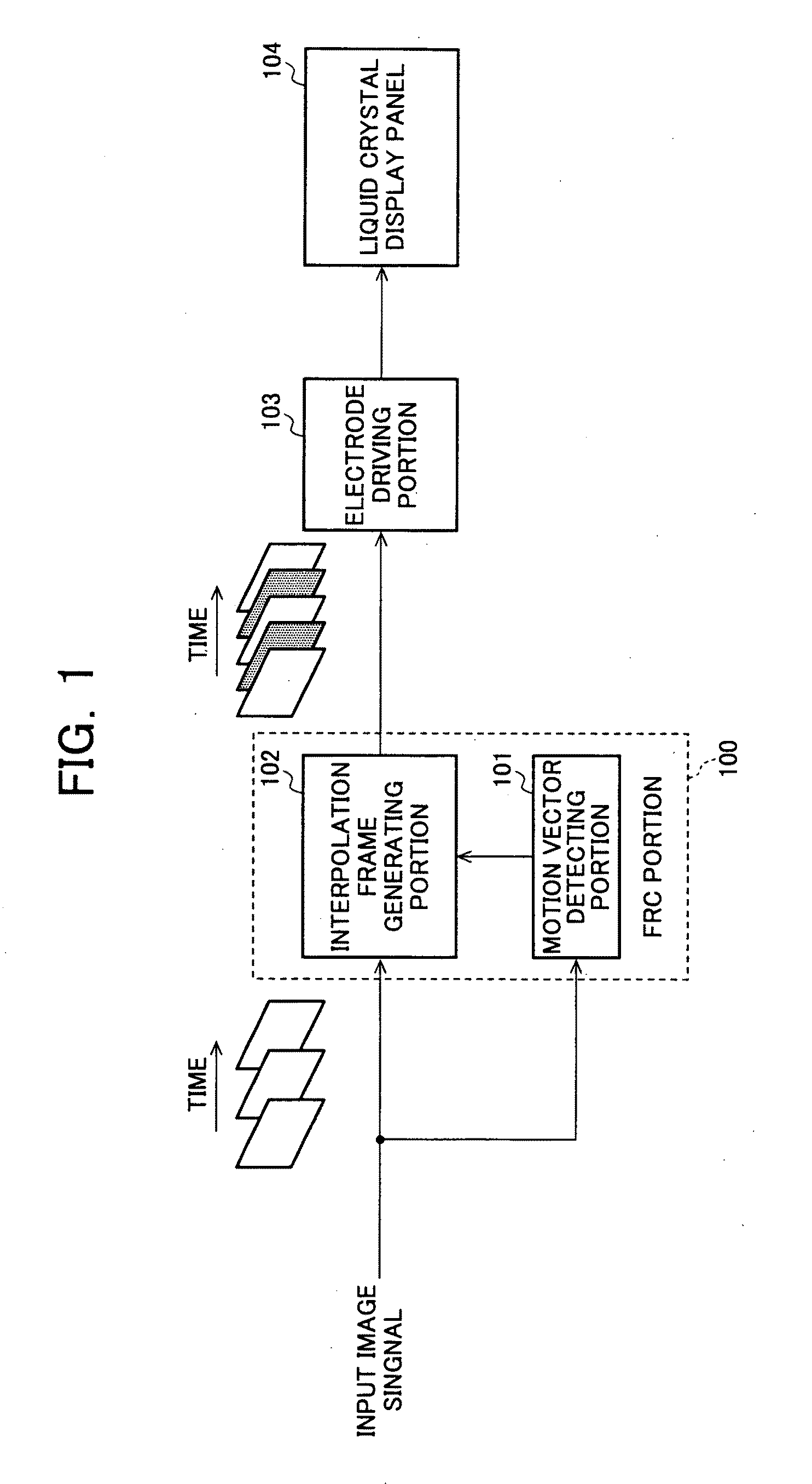
[0126]FIG. 7 is a block diagram of an exemplary main configuration of a liquid crystal displaying device according to the first embodiment of the present invention, and the liquid crystal displaying device includes the FRC portion 10, a movement amount determining portion 14, a controlling portion 15, a switching portion 16, a zero-vector portion 17, an electrode driving portion 18, and a liquid crystal display panel 19. The switching portion 16 is disposed between the motion vector detecting portion 11e and the interpolation vector evaluating portion 11f within the FRC portion 10 and switches over the motion vector from the motion vector detecting portion 11e to the ...

Example

[0136]In a second embodiment of the present invention, when the movement amount between the frames of the input image signal is larger than a predetermined value, the interpolation vector from the interpolation vector evaluating portion 11f is set to zero-vector to make the motion compensation processing of the FRC portion 10 ineffective so that no interpolation can occur between pixels located at different positions.

[0137]FIG. 8 is a block diagram of an exemplary main configuration of a liquid crystal displaying device according to the second embodiment of the present invention, and the liquid crystal displaying device includes the FRC portion 10, the movement amount determining portion 14, the controlling portion 15, the switching portion 16, the zero-vector portion 17, the electrode driving portion 18, and the liquid crystal display panel 19. The switching portion 16 is disposed between the interpolation vector evaluating portion 11f and the interpolation frame generating portion...

Example

[0142]In a third embodiment of the present invention, when the movement amount between the frames of the input image signal is larger than a predetermined value, the interpolation vector from the interpolation vector evaluating portion 11f is set to zero-vector to make the motion compensation processing of the FRC portion 10 ineffective so that no interpolation can occur between pixels located at different positions.

[0143]FIG. 9 is a block diagram of an exemplary main configuration of a liquid crystal displaying device according to the third embodiment of the present invention and the liquid crystal displaying device includes the FRC portion 10, the movement amount determining portion 14, the controlling portion 15, the switching portion 16, the zero-vector portion 17, the electrode driving portion 18, and the liquid crystal display panel 19. The switching portion 16 is disposed between the interpolation vector evaluating portion 11f and the interpolation frame generating portion 12...


PUM


Abstract

The quality of moving picture image with a large moving amount is prevented from deterioration due to moving compensation type frame rate conversion (FRC) processing. The image display device is comprised of an FRC unit (10) that interpolates an image signal subjected to moving compensation processing between frames so as to convert the number of frames of the input image signal, a moving amount judging unit (14) that judges whether a moving amount of the input image signal between the frames is larger than a predetermined value or not, and a control unit (15). The FRC unit (10) is provided with a moving vector detecting unit (11e) that detects a moving vector between the frames of the input image signal, an interpolation vector evaluating unit (11f) that allocates an interpolation vector between the frames on the basis of the moving vector information and an interpolation frame generating unit (12d) that generates an interpolation frame from the interpolation vector. In the case where the moving amount between the frames of the input image signal is larger than the predetermined value, the control unit (15) sets the moving vector detected by the moving vector detecting unit (11e) to be zero-vector, and it invalidates the moving compensation processing of the FRC unit (10).

Description

TECHNICAL FIELD[0001]The present invention relates to an image displaying device and method and an image processing device and method, having a function of converting a frame rate or a field rate, and more particularly, to an image displaying device and an image displaying method performed by the device, and an image processing device and an image processing method performed by the device, that prevent deterioration of the image quality of a moving image including an area in which a movement amount between frames or fields is larger than a predetermined value caused by a motion-compensated rate conversion processing.BACKGROUND OF THE INVENTION[0002]As compared to conventional cathode-ray tubes (CRTs) primarily used for realizing moving images, LCDs (Liquid Crystal Displays) have a drawback, so-called motion blur, which is the blurring of outline of a moving portion perceived by a viewer when displaying a moving image. It is pointed out that this motion blur arises from the LCD displ...

Claims


Application Information

Patent Timeline
IPC IPC(8): H04N7/01
CPCG09G3/20G09G3/3611G09G2310/061H04N7/014G09G2320/106G09G2340/0435H04N7/0132G09G2320/0261
Inventor UENO, MASAFUMIYAMAMOTO, KENICHIROHYOSHII, TAKASHIFURUKAWA, HIROYUKIYOSHIDA, YASUHIRO
Owner SHARP KK
Why Eureka
Try Eureka