Method for Producing Long Obliquely Stretched Film

a technology of oblique stretching and film, which is applied in the direction of manufacturing tools, polarising elements, instruments, etc., can solve the problems of reducing the use efficiency of stretched film, oblique wrinkles or twists, and generating constant cutting loss, so as to prevent the drop in contrast or coloring of the display screen. , the effect of excellent productivity

Active Publication Date: 2010-01-07
ZEON CORP
View PDF9 Cites 15 Cited by
  • Summary
  • Abstract
  • Description
  • Claims
  • Application Information

AI Technical Summary

Benefits of technology

[0020]According to a producing method of the present invention, a wide and long obliquely stretched film can be easily obtained in which a thickness in the width direction is uniform and an orientation axis is uniformly oriented in a direction at 10° or more and 85° or less, preferably 12° or more and 85° or less, more preferably 40° or more and 85° or less, or particularly preferably 51° or more and 85° or less with respect to the width direction. The long stretched film with the obliquely oriented orientation axis is suitable as a retarder of a liquid crystal display device and the like. Specifically, when laminated with other long optical elements used for a liquid crystal display device such as a polarizing plate with an orientation axis inclined at a given angle, by using the stretched film having an orientation axis oblique to the longitudinal direction, lamination by roll-to-roll with other long optical elements can be realized. Since a film having an orientation axis in parallel with the width direction (TD direction) or longitudinal direction (MD direction) of a long film needs diagonal trimming, that leaves a large waste portion. Since the stretched film having an orientation axis oblique to the MD direction obtained by the producing method in the present invention may be trimmed in parallel with the MD direction or TD direction, that leaves little film waste portion, which is excellent in productivity. Also, the retarder obtained by the producing method in the present invention has a wider view angle of its display screen when used in a liquid crystal display device, particularly in a reflective-type liquid crystal display device, and can result in preventing drop in contrast or coloring of the display screen.

Problems solved by technology

However, with this method, even if cutting is done so that the maximum area can be obtained, a cutting loss is generated all the time to lower use efficiency of the stretched film, which is a problem.
However, with these obliquely stretching methods, wrinkles or twists can easily occur obliquely.
Thus, it is substantially impossible to obtain a wide film having a uniform thickness in the width direction and an orientation axis uniformly oriented in an oblique direction at 10° or more and 85° or less.
Thus, it has not been possible to mass-produce a long and wide optical film industrially in which an orientation axis is oriented obliquely (in a direction largely offset from the film width direction or longitudinal direction).

Method used


Image

  • Method for Producing Long Obliquely Stretched Film
  • Method for Producing Long Obliquely Stretched Film
  • Method for Producing Long Obliquely Stretched Film

Examples


example 1

[0097]A pellet of norbornene resin (by Zeon corporation, ZEONOR1420) was molded by a T-die type film extrusion molding machine so as to have a long unstretched film (A) with a width of 1000 mm and a thickness of 130 μm. The unstretched film (A) was taken up by a roll.

[0098]Then, the unstretched film (A) was wound off the roll, supplied to a longitudinal stretching machine, and longitudinally stretched under a stretching condition shown in Table 1 so as to have a longitudinally stretched film (B) with characteristics shown in Table 2. The longitudinally stretched film (B) was taken up by another roll.

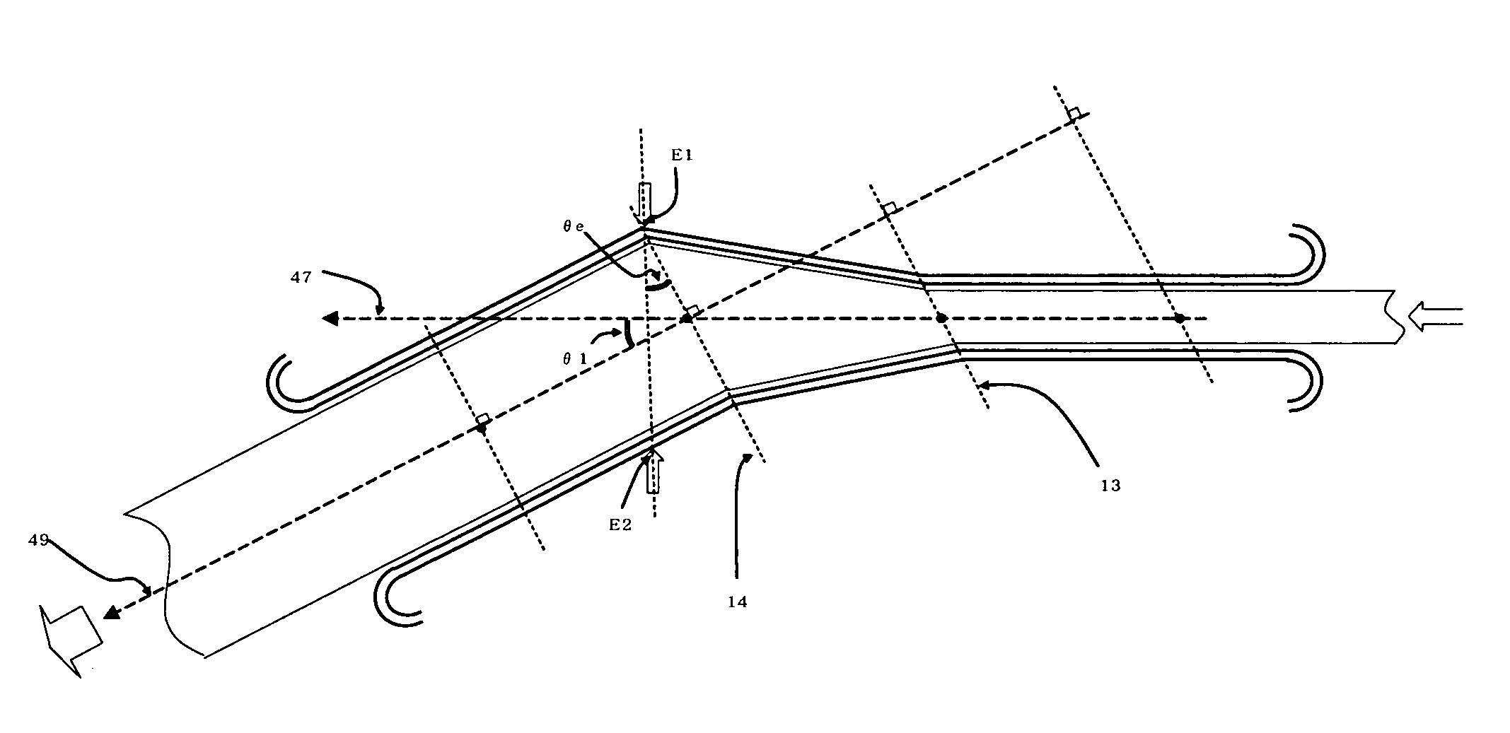
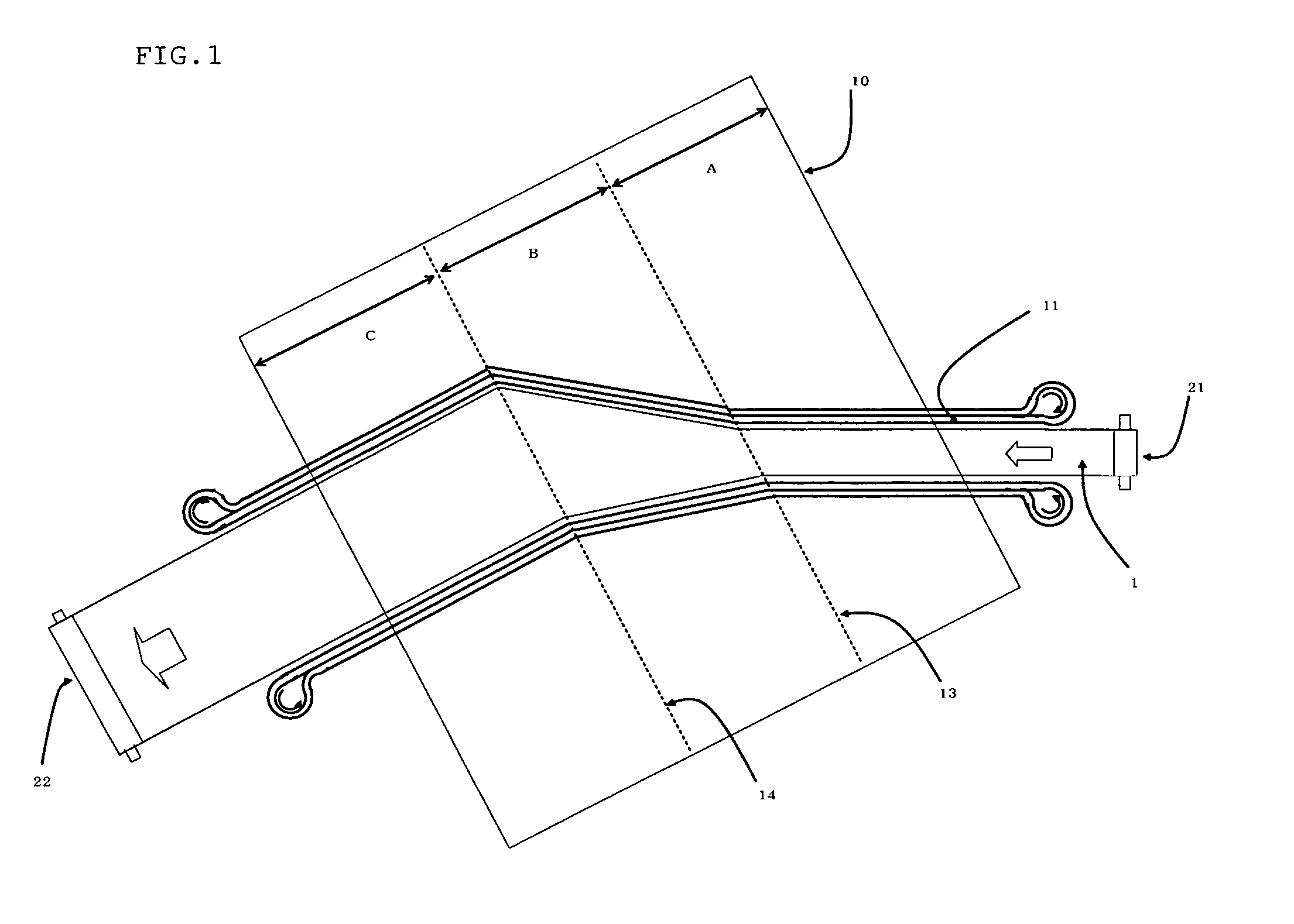
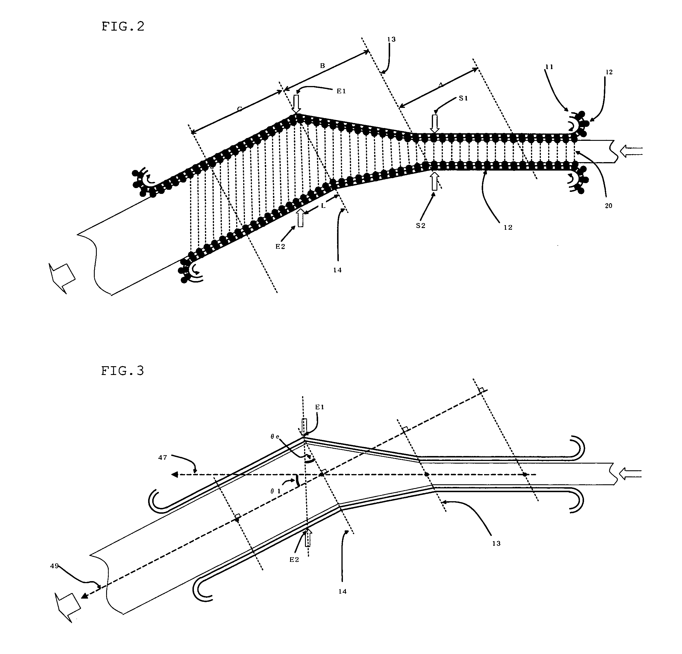
[0099]Moreover, the longitudinally stretched film (B) was wound off the roll, supplied to a tenter stretching machine shown in FIGS. 1 to 3, stretched under the stretching condition shown in Table 1 in a direction obliquely at 10° to the width direction of the longitudinally stretched film (B) so as to have a obliquely stretched film (C), and the film (C) was further taken up by an added...

example 2

[0100]The long longitudinally stretched film (B) obtained in Example 1 was wound off the roll, supplied to a tenter stretching machine, stretched in a direction obliquely at 10° with respect to the width direction of the longitudinally stretched film (B) under the stretching condition shown in Table 1 so as to obtain a obliquely stretched film (D). And the film (D) was taken up by an added roll so as to have a obliquely stretched film winding body. The film (D) had an orientation axis of an average orientation angle of 45° with respect to the width direction and had properties shown in Table 2.

example 3

[0101]The long longitudinally stretched film (B) obtained in Example 1 was wound off the roll, supplied to a tenter stretching machine, stretched in a direction obliquely at 15° with respect to the width direction of the longitudinally stretched film (B) under the stretching condition shown in Table 1 so as to obtain a obliquely stretched film (E). Moreover the film (E) was taken up by an added roll so as to have a obliquely stretched film winding body. The film (E) had an orientation axis of an average orientation angle of 75° with respect to the width direction and had properties shown in Table 2.


PUM

PropertyMeasurementUnit
angleaaaaaaaaaa
angleaaaaaaaaaa
glass transition temperatureaaaaaaaaaa

Abstract

A long obliquely stretched film is obtained having an orientation axis in a direction with an angle θs of 10° or more and 85° or less from a width direction by grasping both side ends in the width direction of a longitudinally stretched film with an average retardation Re1 by grasping means; stretching the film under a condition that a long obliquely stretched film sample with an average retardation Re2 (Re2 is smaller than Re1) can be obtained and traveling speeds of the grasping means are substantially equal at the film both side ends through a preheating zone, a stretching zone and a fixing zone; releasing the both side ends of the film from the grasping means; and taking it up around a winding core.

Description

TECHNICAL FIELD[0001]The present invention relates to a method for producing a long obliquely stretched film, a method for producing a retarder, and a liquid crystal display device comprising the retarder.BACKGROUND ART[0002]In a liquid crystal display device, various retarders are used for optical compensation such as prevention of coloring and expansion of view angles. Retarders used in the liquid crystal display device are in a rectangular shape in general and have an orientation axis in a direction inclined with respect to a side thereof. In a liquid crystal display devices, such a retarder is laminated on a polarization plate such that the orientation axis of the retarder and a polarization transmission axis of the polarization plate get into a desired angle.[0003]As a method of manufacturing a retarder having an orientation axis in a direction inclined with respect to its side as above, such a method is widely known that a transparent resin film (raw material film) is stretche...

Claims


Application Information

Patent Timeline
Patent Type & Authority Applications(United States)
IPC IPC(8): G02F1/1335B29C55/02B32B9/04B29D7/01
CPCB29C55/045B29K2995/0032Y10T428/24479G02B5/3083G02B5/3033Y10T428/31504B29C55/10G02B5/30B29L2011/00B29L2007/00
Inventor ITADANI, MOTOHIROSATO, TAKASHI
Owner ZEON CORP
Why Eureka
Try Eureka