Backlight module

a backlight module and backlight technology, applied in the field of backlight modules, can solve the problems of deteriorating transmission and response speed of liquid crystal on the liquid crystal display panel b>16/b>, and affecting the display properties of the conventional liquid crystal display device, so as to prevent the heat produced

Active Publication Date: 2010-01-07
CHUNGHWA PICTURE TUBES LTD
View PDF22 Cites 26 Cited by
  • Summary
  • Abstract
  • Description
  • Claims
  • Application Information

AI Technical Summary

Benefits of technology

[0008]The object of the present invention is to provide a backlight module, which can prevent the heat produced by the light emitting unit being transmitted upwardly to the reflective sheet.

Problems solved by technology

Besides, the transmittivity and the responding speed of the liquid crystal on the liquid crystal display panel 16 will also deteriorate with time.
That is, after long-term operation, the display properties of the conventional liquid crystal display device will be impaired.

Method used


Image

  • Backlight module
  • Backlight module
  • Backlight module

Examples


Embodiment Construction

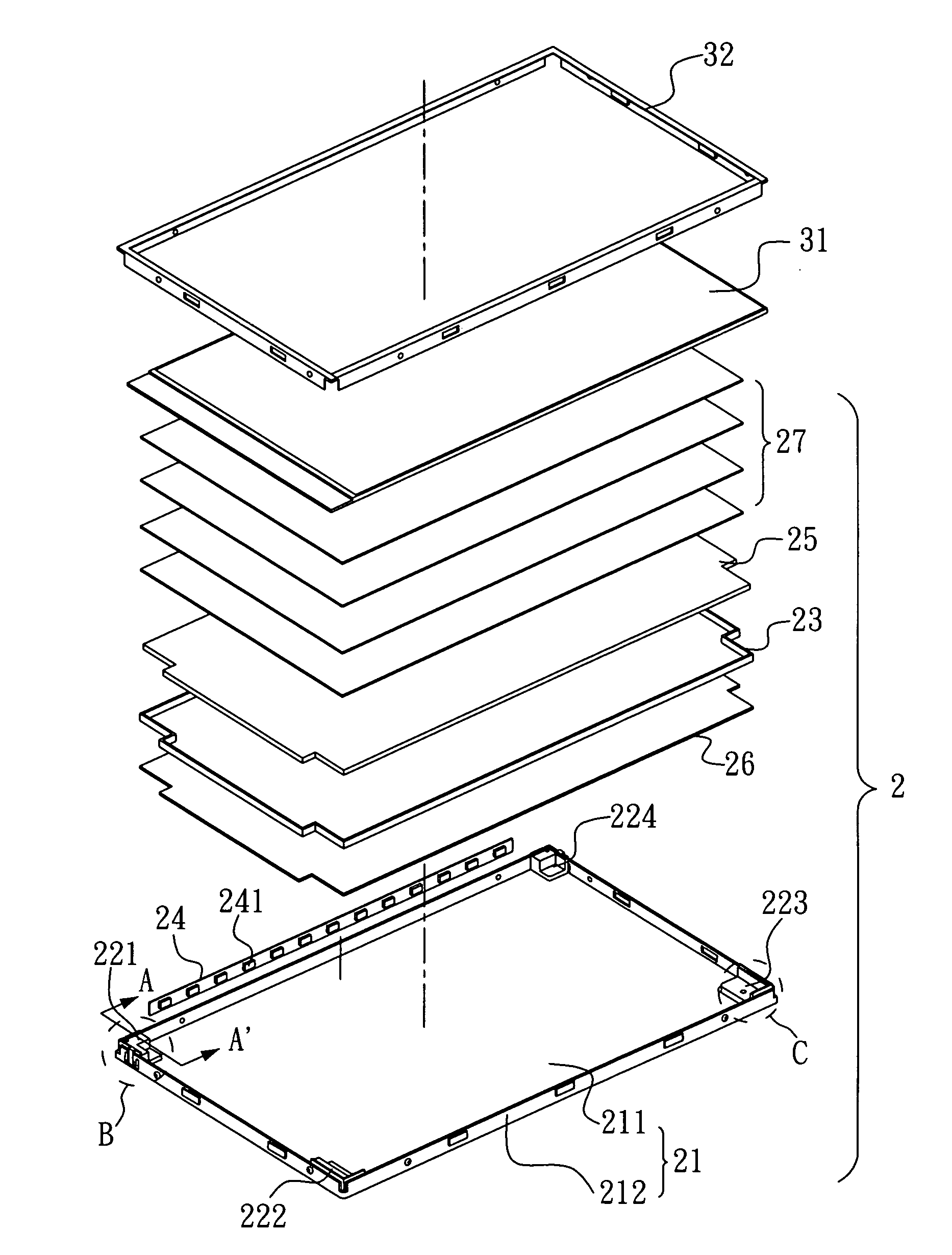
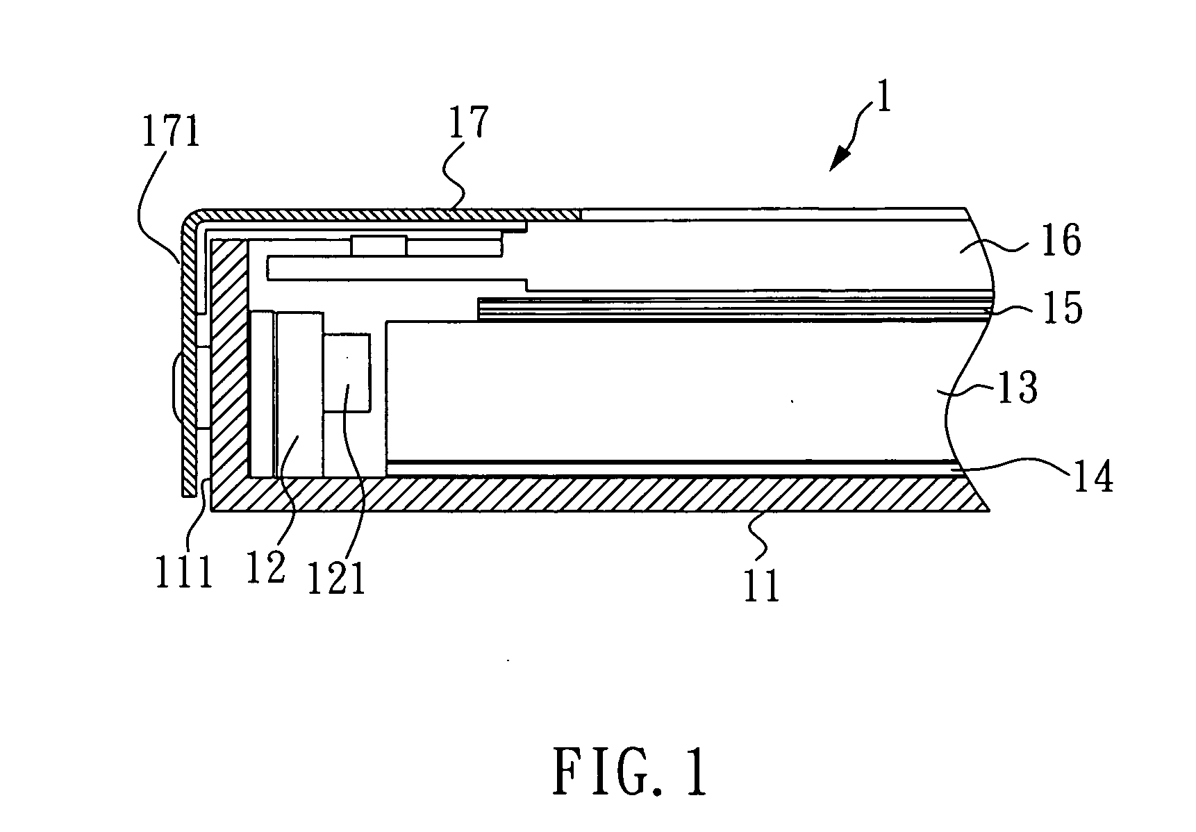
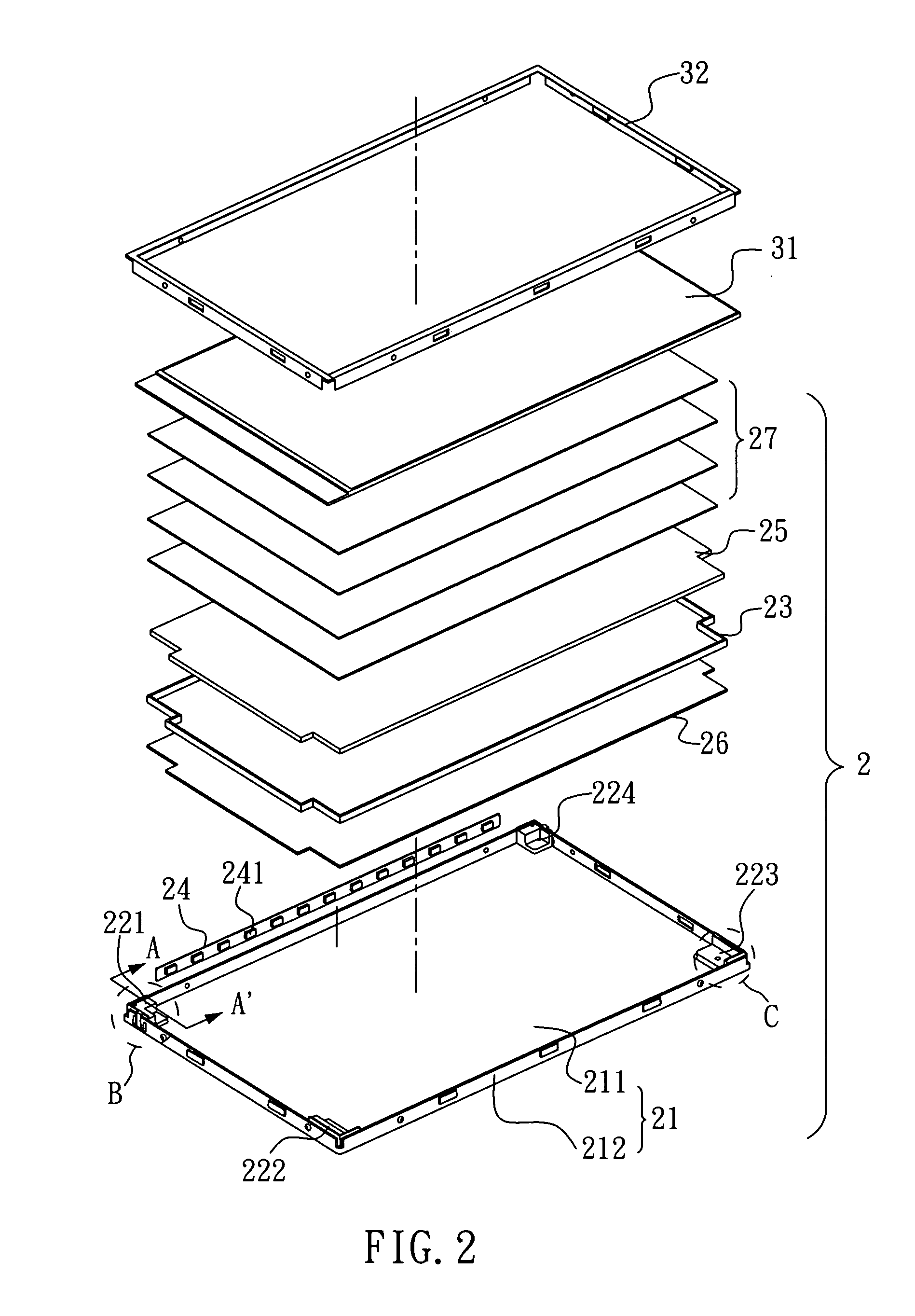
[0018]With reference to FIGS. 2 and 3, wherein FIG. 2 is an exploded view of a liquid crystal display device having the backlight module of the present invention, and FIG. 3 is a cross-sectional view taken along the AA′ plane of FIG. 2, the backlight module 2 of the present invention comprises: a back plate 21, four supporting elements 221, 222, 223 and 224, and a reflective sheet 23 locating on these four supporting elements 221, 222, 223 and 224. Besides, the backlight module 2 of the present invention can further comprise a light emitting diode light bar 24, a light guide plate 25, a heat guide sheet 26, and an optical film set 27.

[0019]As shown in FIGS. 2 and 3, the back plate 21 includes a bottom plate 211 and a side wall 212 protruding from the periphery of the bottom plate 211, for enclosing these four supporting elements 221, 222, 223 and 224, the reflective sheet 23, the light emitting diode light bar 24, the light guide plate 25, the heat guide sheet 26, and the optical fi...


PUM


Abstract

A backlight module, especially a side-edge type backlight module is disclosed. The backlight module comprises: a back plate having plural side walls, plural supporting elements locating on the connecting parts of the plural side walls, and a reflective sheet locating on the plural supporting elements. Therefore, an air space is maintained between the reflective sheet and the back plate of the backlight module. As a result, when the backlight module is operating, the heat produced by the light emitting units will not be transmitted to the reflective sheet of the backlight module during the operation. That is, even after long-term operation, the temperature of the reflective sheet of the backlight module can be maintained at a stable level.

Description

BACKGROUND OF THE INVENTION[0001]1. Field of the Invention[0002]The present invention relates to a backlight module, and more particularly, to a side-edge type backlight module.[0003]2. Description of Related Art[0004]With reference FIG. 1, which is a cross-sectional view of a conventional liquid crystal display device, the conventional liquid crystal display device comprises: a back plate 11, a light emitting diode light bar 12, a light guide plate 13 and a reflective sheet 14. The reflective sheet 14 is located between the light guide plate 13 and the back plate 11. The back plate 11 encloses the light emitting diode light bar 12, a light guide plate 13 and the reflective sheet- 14 therein. Besides, the back plate 11 includes a bottom plate (not shown in the figure) and a side wall 111 protruding upwardly from the periphery of the bottom plate (not shown in the figure). The aforementioned light emitting diode light bar 12 is fixed on the side wall 111. Moreover, the conventional l...

Claims


Application Information

Patent Timeline
Patent Type & Authority Applications(United States)
IPC IPC(8): G09F13/04
CPCG02B6/0055G02B6/0073G02F2001/133628G02F1/133615G02B6/0085G02F1/133628
Inventor LIN, HSIU-YU
Owner CHUNGHWA PICTURE TUBES LTD
Why Eureka
Try Eureka