Control device for hybrid vehicle drive apparatus

a technology for driving apparatuses and control devices, which is applied in the direction of electric propulsion mounting, vehicle sub-unit features, transportation and packaging, etc., can solve the problems of inadequate rattling-free connection, achieve increased engine rotation speed, reduce biased load, and increase the effect of engine rotation speed

Active Publication Date: 2010-01-07
TOYOTA JIDOSHA KK
View PDF3 Cites 34 Cited by
  • Summary
  • Abstract
  • Description
  • Claims
  • Application Information

AI Technical Summary

Benefits of technology

[0030]With the ninth aspect of the invention, the control device operates as follows. When the differential mechanism is placed in the differential state to start-up the engine, the third rotary element is fixedly retained and the rotation speed of the second rotary element is increased by the first electric motor, for thereby increasing the rotation speed of the engine. This enables the engine to start-up without rendering the differential state switching device operative.
[0031]With the tenth aspect of the invention, upon starting up the engine, either one of or both of the first and second electric motors are driven to increase the rotation speed of the engine. This reduces biased load applied on one electric motor.
[0032]With the eleventh aspect of the invention, the

Problems solved by technology

In contrast, if output torque of the second electric motor is less than the given v

Method used


Image

  • Control device for hybrid vehicle drive apparatus
  • Control device for hybrid vehicle drive apparatus
  • Control device for hybrid vehicle drive apparatus

Examples


first embodiment

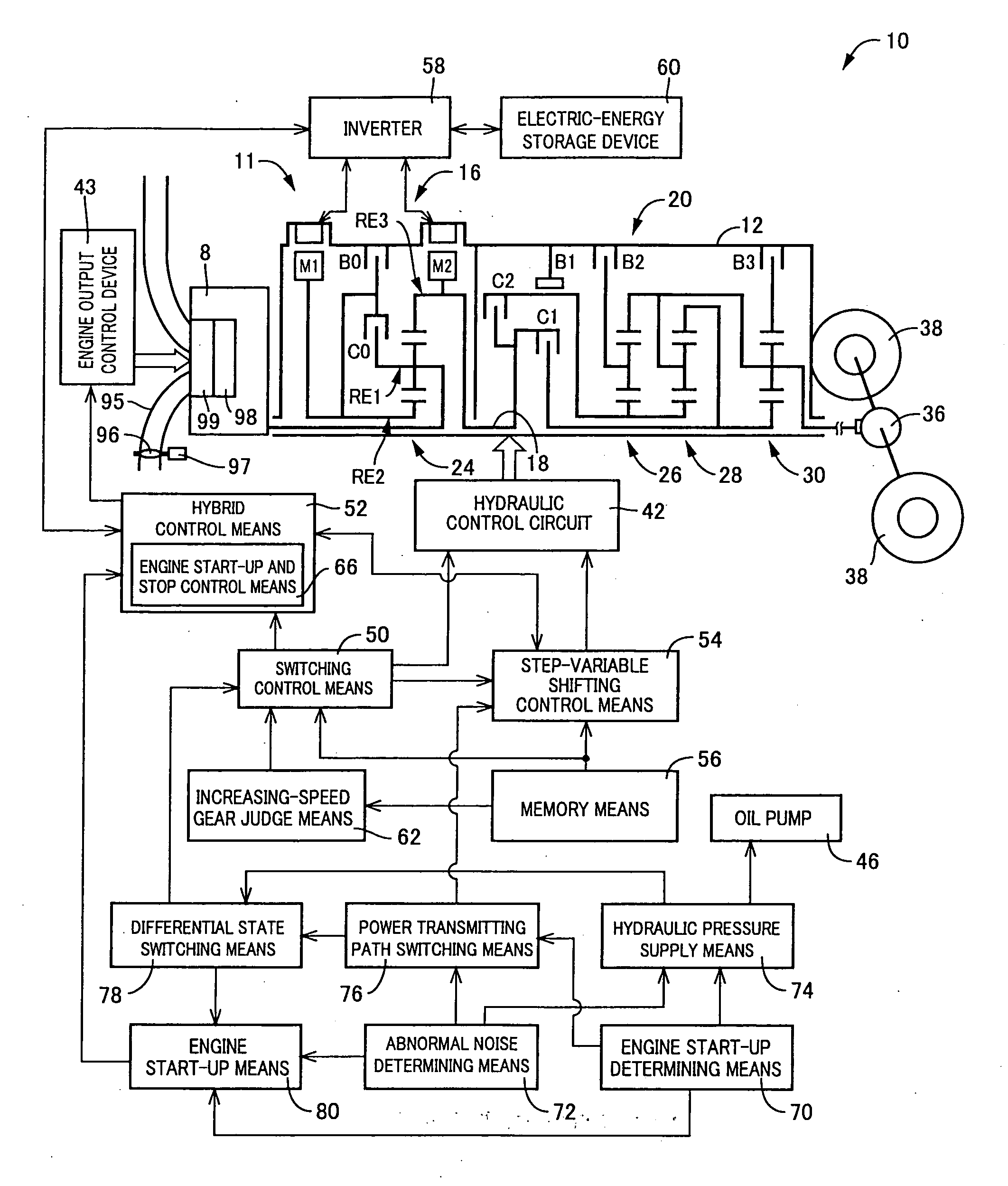
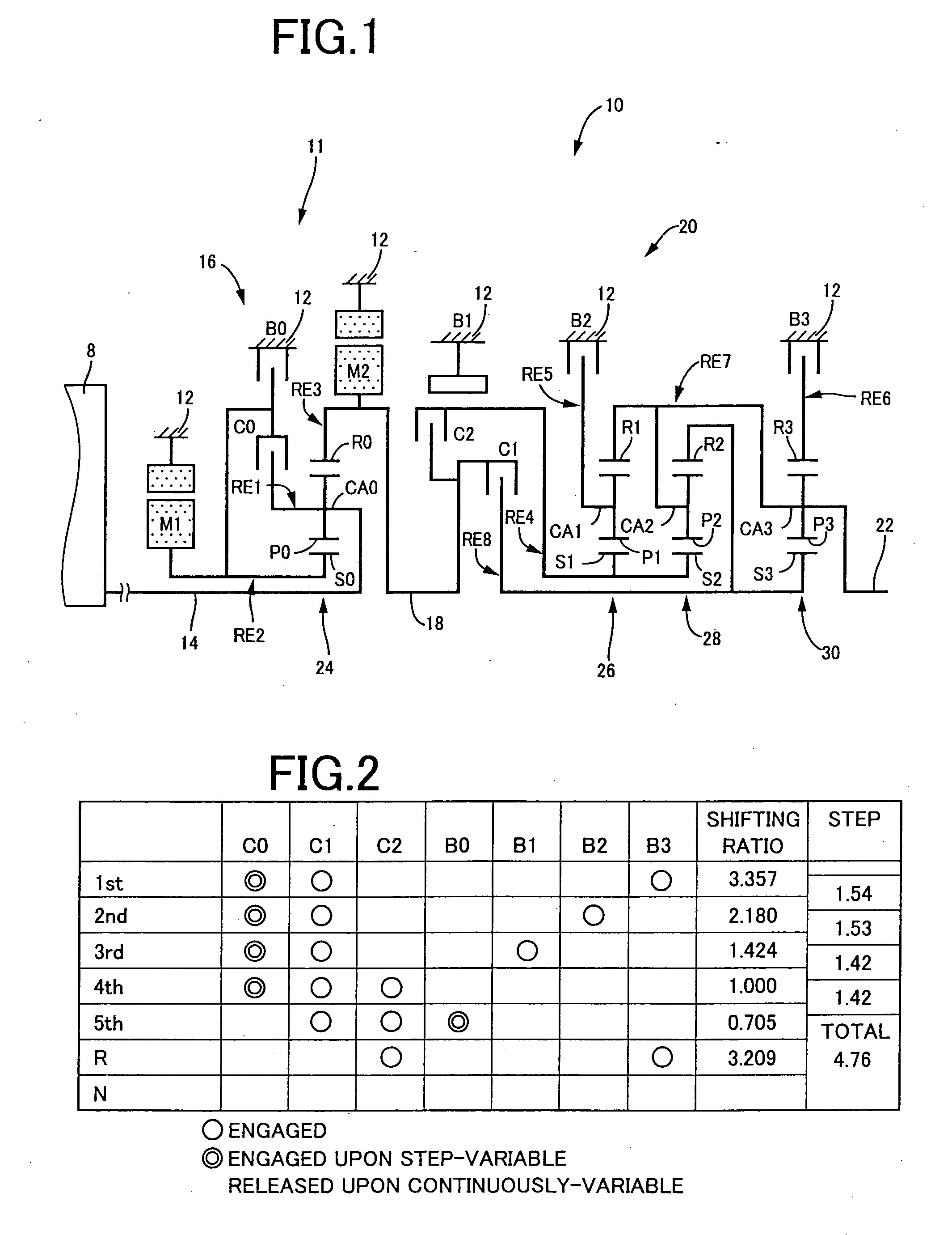
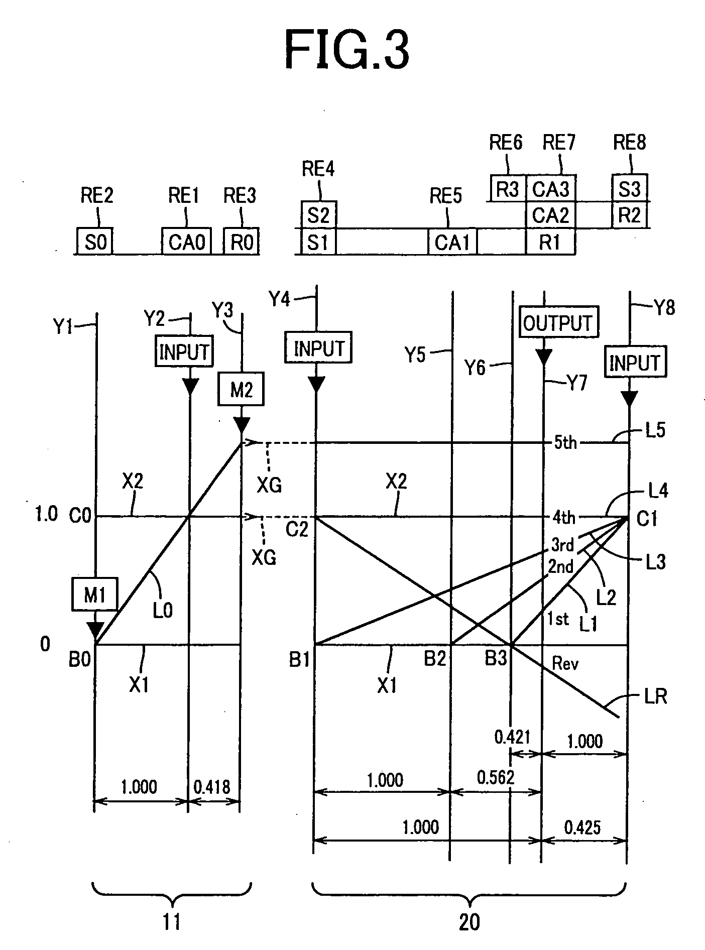
[0050]FIG. 1 is a skeleton view illustrating a shifting mechanism 10, forming part of a drive apparatus for a hybrid vehicle, to which a control device of the present invention is applied. As shown in FIG. 1, the shifting mechanism 10 includes an input shaft 14, a differential portion 11 and an automatic shifting portion 20, which are connected to an output shaft 22 in series. The input shaft 14 is disposed in a transmission case (hereinafter referred to as “case 12”) mounted on a vehicle body as a non-rotary member so as to extend on a common axis to function as an input rotary member. The differential portion 11 is coupled to the input shaft 14 in a direct connection or through a pulsation absorbing damper (vibration damping device) which is not shown. The automatic shifting portion 20 is connected to a power transmitting path between the differential portion 11 and drive wheels 38 (see FIG. 7) via a power transmitting member (power transmitting shaft) 18 to serve as an output rot...

second embodiment

[0195]During a phase in which the engine 8 is halted, the engine rotation speed NE transits a resonating region involved in the engine rotation speed region. Therefore, like the first embodiment described above, even when stopping the engine 8 during the halt of the vehicle, rattling gear noise tends to occur with a level impairing a comfort of a vehicle occupant. To address such an issue, a control operation is executed for minimizing rattling gear noise in a manner as described below.

[0196]The second embodiment represents a structure wherein the electronic control device 40 of the first embodiment is replaced by an electronic control device 110. FIG. 15 is a view, corresponding to FIG. 7, which represents a functional block diagram illustrating a major control function to be executed with the electronic control device 110 of the second embodiment. Hereunder, the second embodiment will be described below with a focus on points differing from those of the first embodiment.

[0197]The ...


PUM


Abstract

A control device for hybrid vehicle drive apparatus is disclosed. Upon receipt of a start-up request on an engine (8), if a determination is made that a rattling gear noise in a power distributing mechanism (16) exceeds a given value, first and second clutches (C1 and C2) are disengaged to cause a power transmitting path to be placed in a power interrupting state, and the first and second clutches (C1 and C2) are engaged to cause the power transmitting path to be placed in a non-differential state. Thus, engine start-up is initiated. This allows the engine (8) to be started up with a limited occurrence of rattling between gears incorporated in the power distributing mechanism (16) with a reduction in rattling gear noise.

Description

TECHNICAL FIELD[0001]The present invention relates to control devices for hybrid vehicle drive apparatuses. More particularly, it relates to a technology of minimizing the occurrence of noise impairing a comfort of a vehicle occupant in a hybrid vehicle drive apparatus having a differential mechanism operative to perform a differential action, and an electric motor.BACKGROUND ART[0002]There has been known a hybrid vehicle drive apparatus including an engine, a first electric motor, a second electric motor and a planetary gear mechanism which has a first rotary element connected to the engine, a second rotary element connected to the first electric motor and a third rotary connected to a power transmitting path connected to drive wheels, the second electric motor being connected to the power transmitting path. Such a hybrid vehicle drive apparatus is disclosed in, for instance, FIG. 1 of Patent Publication 1 (Japanese Patent Application Publication No. 2006-242096). With such a hybri...

Claims


Application Information

Patent Timeline
IPC IPC(8): F16H61/66B60K6/445B60K6/547B60L50/16B60W10/02B60W10/06B60W10/08B60W10/30B60W20/00F16H59/72F16H59/74F16H61/02F16H61/68F16H61/684F16H61/686F16H63/50
CPCB60K1/02Y10T477/653B60K6/445B60L2240/421B60L2240/441B60L2240/445B60L2240/485B60L2240/486B60W10/02B60W10/06B60W10/08B60W10/115B60W20/00B60W2510/0604B60W2510/0638B60W2510/0676B60W2510/068B60W2510/0685B60W2510/081B60W2510/1005B60W2510/107B60W2510/1075B60W2520/10B60W2520/105B60W2520/28B60W2530/10B60W2540/10B60W2540/12B60W2710/0616F16H57/0006F16H2061/6603Y02T10/6239Y02T10/6286Y02T10/642B60Y2400/435Y10S477/906Y10T477/23B60K6/365Y02T10/62Y02T10/64B60K2006/268B60W20/15
Inventor IWASE, YUJIKAKINAMI, TAKUMATABATA, ATSUSHI
Owner TOYOTA JIDOSHA KK
Why Eureka
Try Eureka