
Bone cement conductor device

Inactive Publication Date: 2010-01-07
GM DOS REIS JUNIOR
View PDF5 Cites 13 Cited by
  • Summary
  • Abstract
  • Description
  • Claims
  • Application Information

AI Technical Summary

Benefits of technology

[0019]More specifically, it is an objective of the present invention to provide a bone or surgical cement conductor device, that allows the application of this material in the bone structure during surgical processes adequately and safely, since it comprises an arrangement capable of promoting an efficient and safer connection between the cement applicator device and the bone screw.
[0020]Further, another objective of the present invention is a cement conductor device that presents a simple structure that is easy to manufacture and to assemble.
[0021]Another objective of the present invention is to provide a bone cement conductor device comprising an arrangement that is easy for surgeons to handle during surgical processes, eliminating any risk of leakage and, ensuring that the material applied be introduced only in the desired place.

Problems solved by technology

However, the problem of patients suffering from this kind of disease is worsened when the need arises for the introduction and attachment of osseous synthesis of the bone plate kind, intervertebral spacers and implants, among others, which are fixed to the bone structures by means of bone screws.
In such situations, it is noted that the bone screws, when introduced into the bone structure of the patient with osteoporosis, are not fixed safely.
Normally, the bone screws end up loose, lax, damaging the bone structure, since these bones are relatively hollow, that is, there is no bone matter to anchor the bone screws.
As a result, it is not possible to establish a firm, safe and stable attachment of the bone screw.
However, as persons skilled in the art will appreciate, this kind of procedure may lead to certain drawbacks for doctors and chiefly for patients, since: i) the cement may harden before the due positioning of the bone screw; ii) it requires a relatively large incision in the patient; iii) it increases the risk of infection due to the size of the incisions; iv) it requires extra attention in rebuilding the bone structure with cement; v) there is a risk that the bone cement may accidentally be applied in an inappropriate place, which may compromise the patient's health.
As can be noted, this technique of applying and manual filling of the bone structures with cement generates a series of problems for patients, because it increases the surgery time, the risk of infection due to the size and prolonged exposure time of the incision, the post-operation recovery time and, principally, it may lead to inadequate positioning of the bone screws.
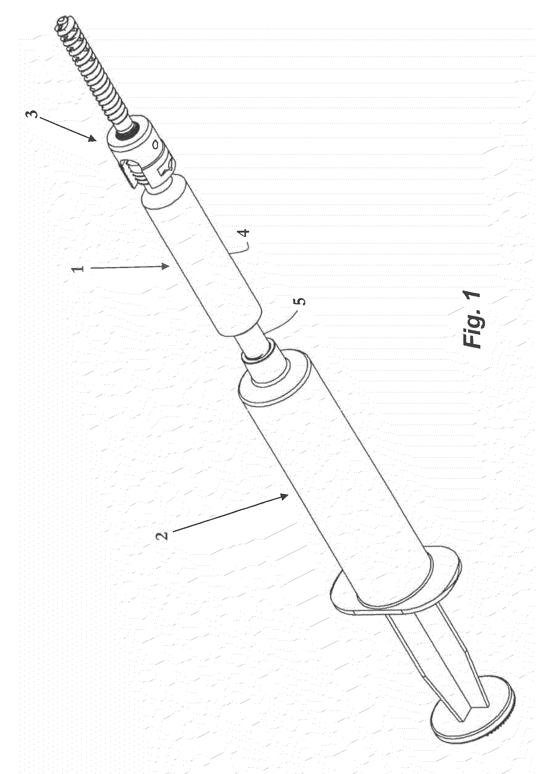
Although it solves the problem of hardening of the cement before introducing and positioning the bone screw, since the cement is only introduced after the due positioning of the bone screw in the bone structure, it can be verified that in practice such disposition is neither efficient nor easy to apply.
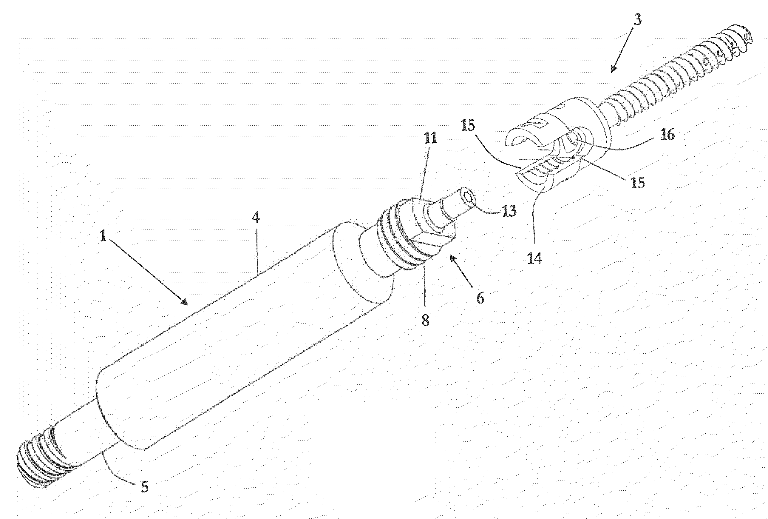
More specifically, the difficulties observed in practice are related to incompatibility of connections between the cement injection device and the bone screw, but principally in relation to the efficiency and safety during the process of applying the cement in the bone structure.
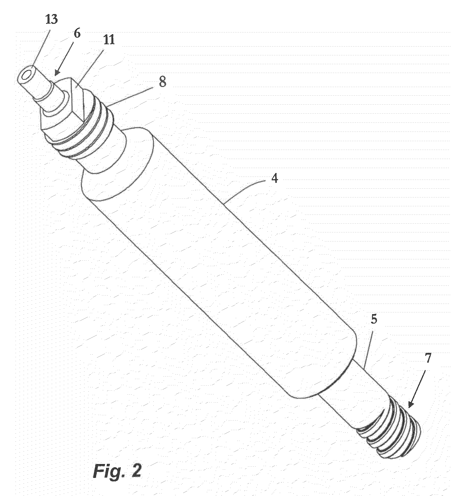
Additionally, since there are no appropriate devices for conducting and adequately applying cement, it can be seen that doctors face a major hurdle in obtaining a precise alignment between the opening of the material extraction of the injection device and the bone screw channel.
Accordingly, it can be verified that all devices and procedures of applying bone cement or surgical cement known in the state of the art reveal problems relating to risks of causing leakage during surgical procedures, allowing the material to be applied at inappropriate sites inside the incisions.

Method used


Image

  • Bone cement conductor device
  • Bone cement conductor device
  • Bone cement conductor device

Examples


Embodiment Construction

[0029]According to FIG. 1, it is noted that the bone cement conductor device (1) that is the object of the present invention, is an element that connects the injection device (2) and the bone screw connector (3). More particularly, the conductor device (1) comprises an outer encasement (4) that involves a conductor body (5) whose ends (6, 7) are exposed for due encasement with the injection device (2) and the bone screw (3).

[0030]As persons skilled in the art will appreciate, the injection devices (2) and the bone screws (3) are known surgical instruments that have been used for years and, for this reason, it is understood that there is no need to provide more specific details thereon. It is important to point out that the injection devices (2) are provided with an applicator nozzle provided with connection means of the thread type, and the bone screws (3) have an end, called interface connector, which can be the very head of the screw itself. These connectors comprise a cylindrical...


PUM


Abstract

A bone cement conductor device provides for the application and the safe and effective filling of bone cement during surgical treatment procedures in patients suffering from osteoporosis. More specifically, the device is constituted by a structure that is easy to manufacture and handle, and that facilitates surgical processes and treatments, demanding less effort of surgeons. The device includes an outer encasement with a conductor body being provided with interlink and connection mechanisms with a cement injection device and a bone screw that eliminate any risk of leakage or incorrect application of the cement in the patient's bones.

Description

FIELD OF THE INVENTION[0001]The present invention refers to a cement conductor device for processes of attaching osseous synthesis in patients whose bone structure is compromised and lacks the sufficient resistance for attaching bone screws, such as patients suffering from osteoporosis.[0002]More particularly, the present invention refers to a guide that interlinks the cement injection device to the bone screws, said conductor device having structural characteristics that ensure the application of cement in the damaged bone structures by way of the body of the bone screw, which is fixed adequately in the desired position and, also, safely and effectively.[0003]Additionally, the cement conductor device, that is the object of the present invention, comprises connection mechanisms which conduct the cement between the applicator device and the bone screw efficiently and safely, eliminating the risks of leakage of the material during application.BACKGROUND OF THE INVENTION[0004]As known ...

Claims


Application Information

Patent Timeline
IPC IPC(8): A61B17/58
CPCA61B17/7098A61B17/7032A61B17/8816
Inventor MARINS DOS REIS, JR., GERALDO
Owner GM DOS REIS JUNIOR
Learn More