Instruments and methods for inserting artificial intervertebral implants

Inactive Publication Date: 2010-01-07
HOWMEDICA OSTEONICS CORP
View PDF99 Cites 19 Cited by
  • Summary
  • Abstract
  • Description
  • Claims
  • Application Information

AI Technical Summary

Benefits of technology

[0028]In an alternative embodiment, instead of or in addition to a template, the present invention may include a midline marker. The midline marker is preferably used for determining a midline of a disc space between two vertebrae. The midline marker preferably has a cruciform shape with a first vertical extension, a second vertical extension, a first lateral extension, and a second lateral extension. The midline marker also preferably has a leading face and a trailing face. The leading face may have a concave curved surface that extends between the first and second lateral arms. The first lateral arm preferably has a first barbed spike projecting therefrom, and the second lateral arm preferably has a second barbed spike projecting therefrom. The midline marker also may include a button projecting from the rear surface thereof, which is connected to the midline marker via connector segment. This button may facilitate connection of the midline marker to a handle.
[0029]In certain preferred embodiments of the present invention, each of the top and bottom elements of the implant has an anterior wall that preferably connects the anterior ends of the protrusions on the element. The ant

Problems solved by technology

This degeneration of this critical disc material, from the hydrated, elastomeric material that supports the separation and flexibility of the vertebral bones, to a flattened and inflexible state, has profound effects on the mobility (instability and limited ranges of appropriate motion) of the segment, and can cause significant pain to the individual suffering from the condition.
Unfortunately, until the ad

Method used


Image

  • Instruments and methods for inserting artificial intervertebral implants
  • Instruments and methods for inserting artificial intervertebral implants
  • Instruments and methods for inserting artificial intervertebral implants

Examples


Embodiment Construction

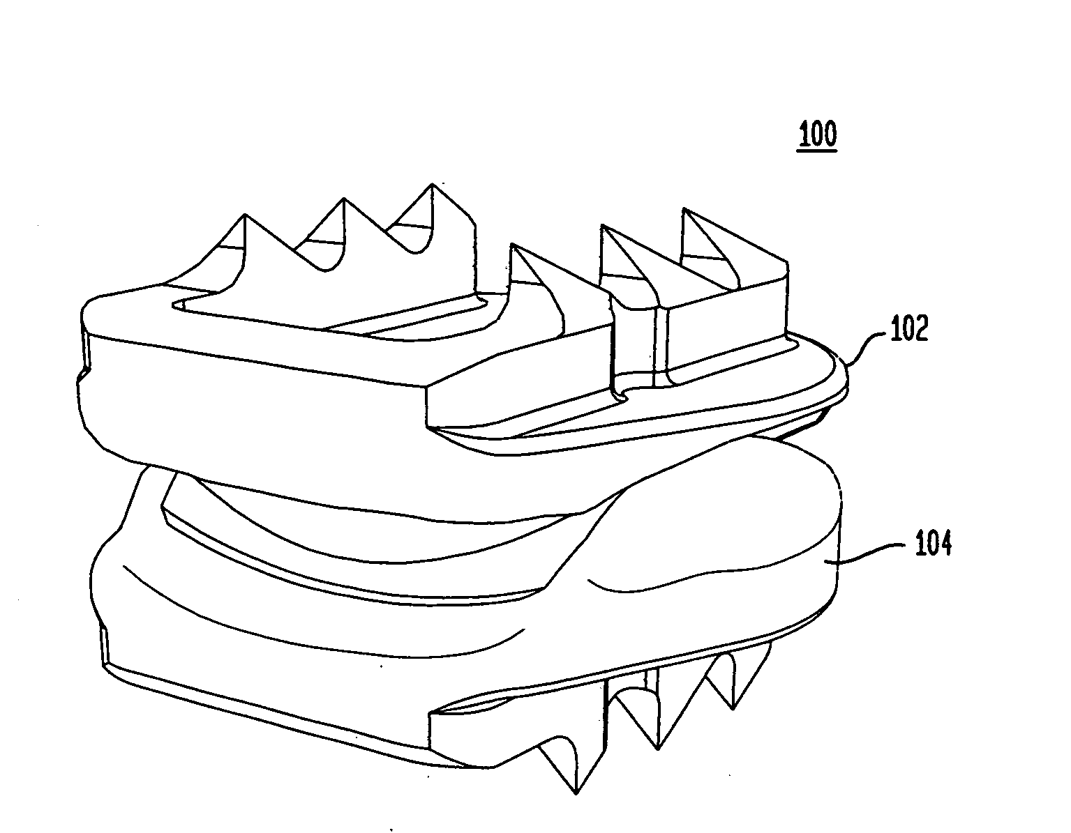
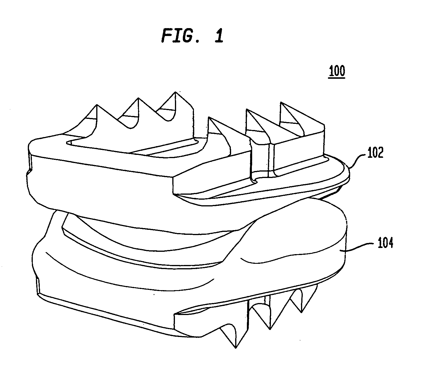
[0123]Referring to FIG. 1, in certain preferred embodiments of the present invention, an intervertebral disc implant 100 includes a top element 102 and a bottom element 104. As will be described in more detail below, the top and bottom elements 102, 104 have opposing articulating surfaces that engage one another. The intervertebral disc implant is adapted to be inserted into a disc space between adjacent vertebrae.

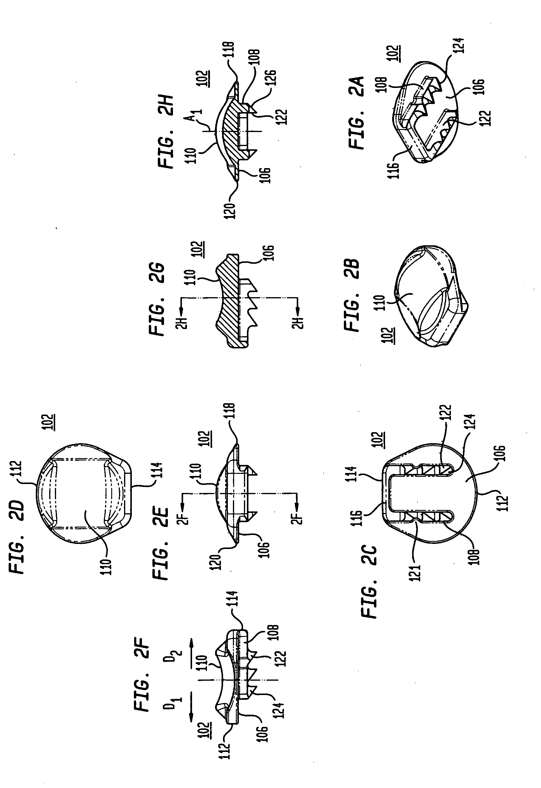
[0124]Referring to FIGS. 2A-2H, the top element 102 includes a first bone engaging surface 106 having protrusions 108A, 108B and a second articulating surface 110. Referring to FIGS. 2C and 2D, the top element has a posterior end 112 and an anterior end 114. As shown in FIGS. 2A and 2C, the two protrusions 108 are interconnected by an anterior wall 116 that extends along the anterior end 114 of the top element. The anterior wall preferably serves as a vertebral body stop to prevent over insertion of the intervertebral disc implant and / or posterior migration of the implant....


PUM


Abstract

Apparatus and methods for preparing a disc space and inserting an intervertebral disc implant therein are disclosed. Among the various instruments disclosed are a midline marker, a reference pin drill and insertion guide, a fin drill guide, a chisel guide, a sizer, a serrated broach, an implant dispenser, and an implant insertion tool. Methods of utilizing these tools are also disclosed.

Description

CROSS-REFERENCE TO RELATED APPLICATIONS[0001]This application claims the benefit of the filing date of U.S. Provisional Patent Application No. 61 / 011,554 filed Jan. 18, 2008, the disclosure of which is hereby incorporated herein by reference.[0002]The present application is related to U.S. patent application Ser. No. 11 / 439,808, entitled “Intervertebral Disc and Insertion Methods Therefor,” filed May 24, 2006, which claims the benefit of the filing dates of U.S. Provisional Patent Application Nos. 60 / 790,415, filed Apr. 7, 2006, 60 / 721,053, filed Sep. 27, 2005, 60 / 701,306, filed Jul. 21, 2005 and 60 / 685,295, filed May 27, 2005, the disclosures of which are hereby incorporated by reference herein.[0003]The present application also relates to U.S. Pat. No. 6,908,484, entitled “Cervical Disc Replacement” and filed on Mar. 6, 2003; U.S. Pat. No. 6,994,728, entitled “Cervical Disc Replacement Method” and filed on Feb. 11, 2004; United States Patent Application Publication No. 2004 / 017685...

Claims


Application Information

Patent Timeline
IPC IPC(8): A61B17/90A61B17/58A61B17/88
CPCA61B17/1604A61F2002/4687A61B17/1757A61F2/0095A61F2/4425A61F2/4611A61F2/4657A61F2/4684A61F2002/30131A61F2002/30301A61F2002/30713A61F2002/30714A61F2002/30841A61F2002/30884A61F2002/30904A61F2002/4619A61F2002/4624A61F2230/0013A61F2230/0095A61F2250/0087A61F2250/0089A61B17/1671A61F2/4603A61F2002/3071A61F2002/4622A61F2002/4658A61F2002/7615
Inventor DUDASIK, MICHAEL W.
Owner HOWMEDICA OSTEONICS CORP
Why Eureka
Try Eureka