Fan variable area nozzle with cable actuator system

a variable area and actuator technology, applied in the direction of machines/engines, sustainable transportation, transportation and packaging, etc., can solve the problems of significant weight savings and uncomplicated operation, and achieve the effect of increasing or decreasing the cable length, increasing and decreasing the exit area of the fan nozzle, and saving weigh

Active Publication Date: 2010-01-14
RTX CORP
View PDF28 Cites 28 Cited by
  • Summary
  • Abstract
  • Description
  • Claims
  • Application Information

AI Technical Summary

Benefits of technology

[0009]The actuator system engages an end segment of the cable such that the cable may be spooled and unspooled to effectively increase or decrease the cable length between a spool and a fixed attachment to increase and decrease the fan nozzle exit area. The bypass flow permits unilateral operation of the FVAN such that the bypass flow operates to diverge the flaps. This results in a significant weight savings and uncomplicated operation.
[0010]The present invention therefore provides an effective, lightweight fan variable area nozzle for a gas turbine engine.

Problems solved by technology

This results in a significant weight savings and uncomplicated operation.

Method used


Image

  • Fan variable area nozzle with cable actuator system
  • Fan variable area nozzle with cable actuator system
  • Fan variable area nozzle with cable actuator system

Examples


Embodiment Construction

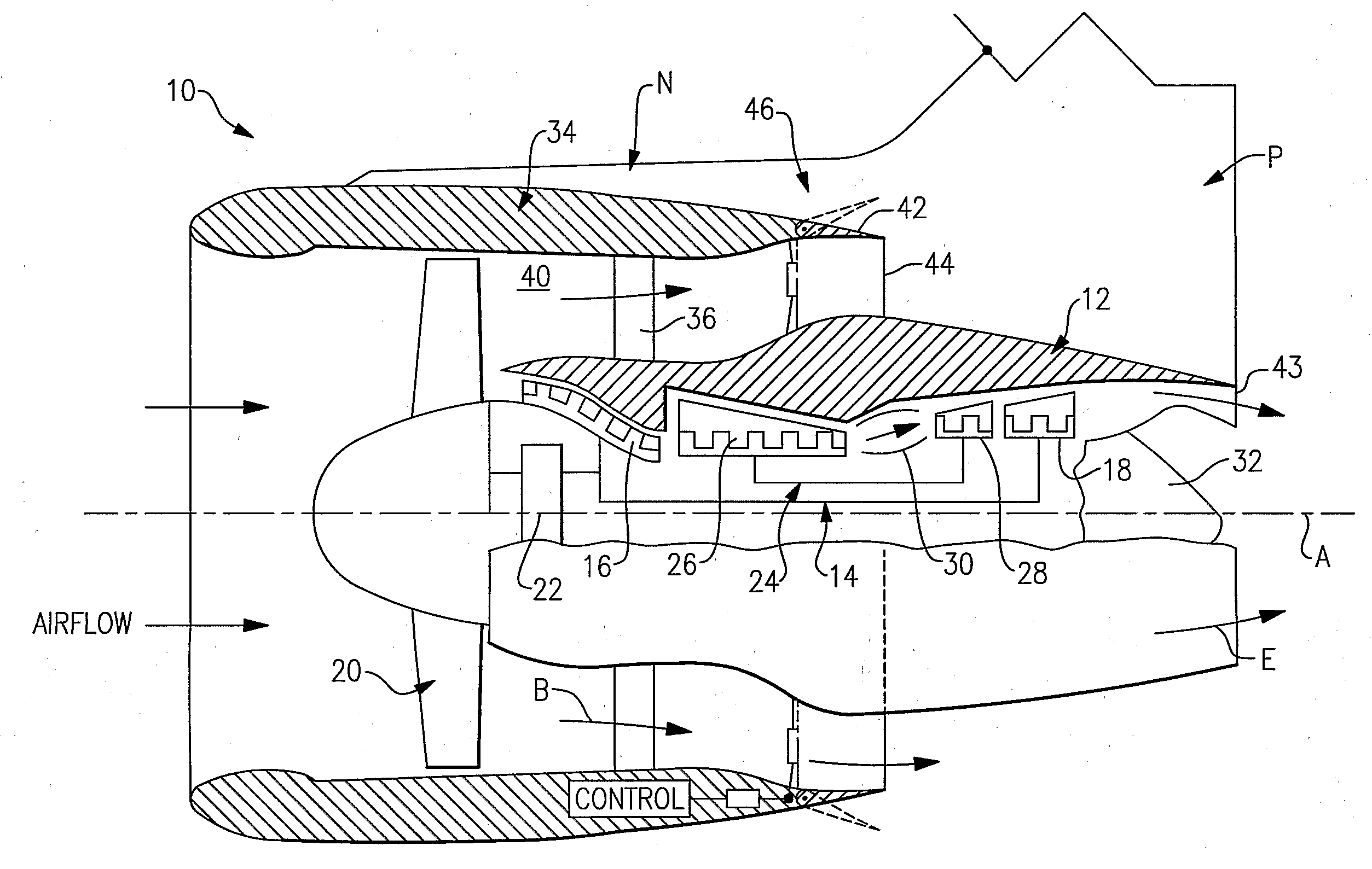
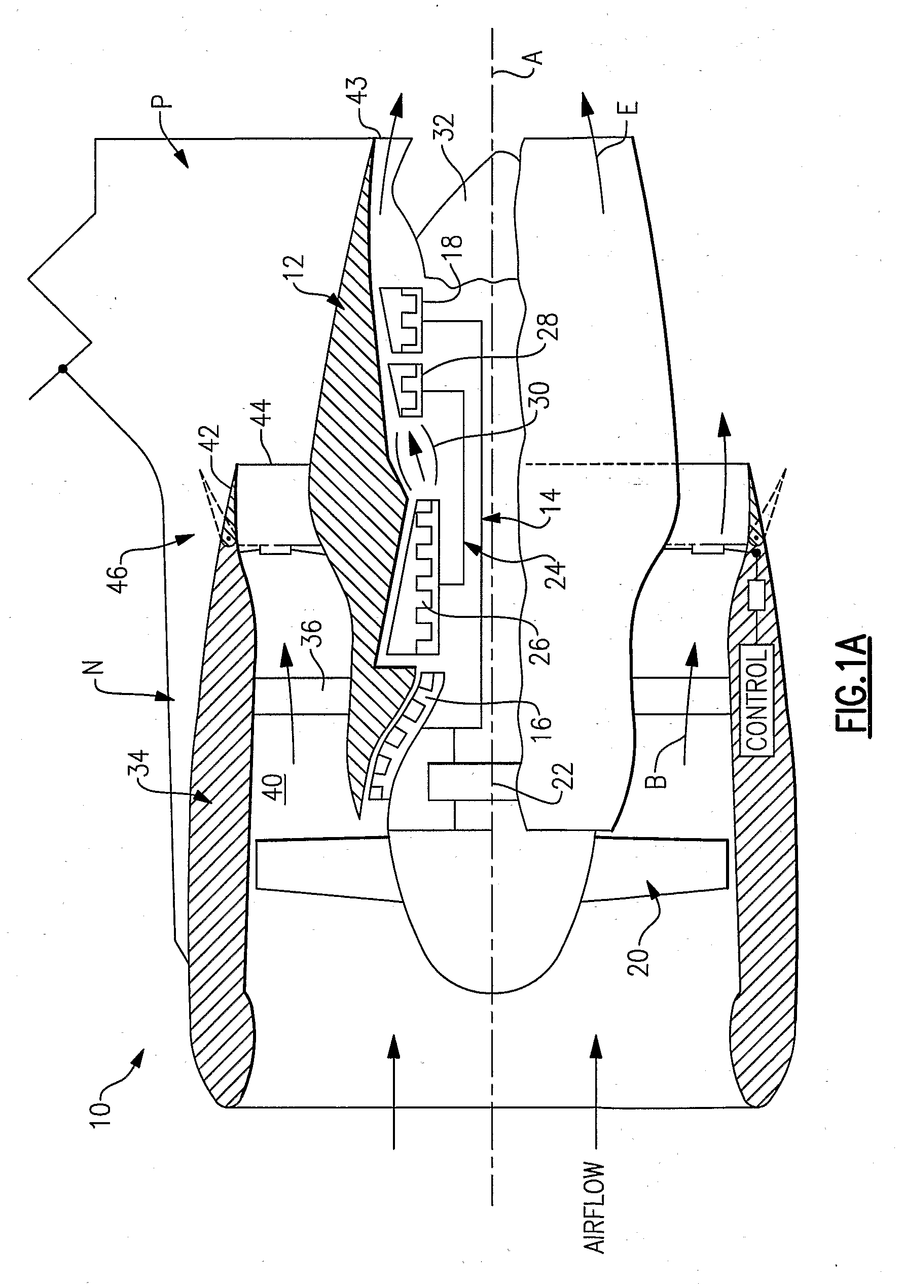
[0017]FIG. 1A illustrates a general partial fragmentary schematic view of a gas turbofan engine 10 suspended from an engine pylon P within an engine nacelle assembly N as is typical of an aircraft designed for subsonic operation.

[0018]The turbofan engine 10 includes a core engine within a core nacelle 12 that houses a low spool 14 and high spool 24. The low spool 14 includes a low pressure compressor 16 and low pressure turbine 18. The low spool 14 drives a fan section 20 connected to the low spool 14 through a gear train 22. The high spool 24 includes a high pressure compressor 26 and high pressure turbine 28. A combustor 30 is arranged between the high pressure compressor 26 and high pressure turbine 28. The low and high spools 14, 24 rotate about an engine axis of rotation A.

[0019]The engine 10 is preferably a high-bypass geared turbofan aircraft engine. Preferably, the engine 10 bypass ratio is greater than ten (10), the fan diameter is significantly larger than that of the low ...


PUM


Abstract

A fan variable area nozzle (FVAN) includes a flap driven through a cable which circumscribes the fan nacelle. The cable is strung through a multiple of flaps to define a flap set of each circumferential sector of the EVAN. An actuator system includes a compact high power density electromechanical actuator which rotates a spool to deploy and retract the cable and effectively increase or decrease the length thereof between the spool and a fixed attachment to increase and decrease the fan nozzle exit area.

Description

BACKGROUND OF THE INVENTION[0001]The present invention relates to a gas turbine engine, and more particularly to a turbofan gas turbine engine having a cable driven fan variable area nozzle structure within the fan nacelle thereof.[0002]Conventional gas turbine engines include a fan section and a core engine with the fan section having a larger outer diameter than that of the core engine. The fan section and the core engine are disposed sequentially about a longitudinal axis and are enclosed in a nacelle. An annular path of primary airflow passes through the fan section and the core engine to generate primary thrust.[0003]Combustion gases are discharged from the core engine through a primary airflow path and are exhausted through a core exhaust nozzle. An annular fan flow path, disposed radially outwardly of the primary airflow path, passes through a radial outer portion between a fan nacelle and a core nacelle and is discharged through an annular fan exhaust nozzle defined at least...

Claims


Application Information

Patent Timeline
Patent Type & Authority Applications(United States)
IPC IPC(8): F02K3/02
CPCF02K1/1207F02K1/15B60C23/0496B60C23/0408F02K3/06Y02T50/60
Inventor CHAUDHRY, ZAFFIR
Owner RTX CORP
Why Eureka
Try Eureka