Nozzle Diffuser Mixer

a technology of diffuser mixer and nozzle, which is applied in the direction of engine components, mechanical equipment, machines/engines, etc., can solve the problems of inability to manufacture and package, and inability to meet the needs of production and packaging

Inactive Publication Date: 2010-01-14
GM GLOBAL TECH OPERATIONS LLC
View PDF9 Cites 74 Cited by
  • Summary
  • Abstract
  • Description
  • Claims
  • Application Information

AI Technical Summary

Benefits of technology

[0004]Exemplary embodiments of the present invention are directed towards an apparatus and method for control of fluid flow through a conduit of an exhaust system of an engine, particularly prior to an exhaust treatment device. In one embodiment, a fluid flow control device for receiving and guiding exhaust gas from an engine towards an exhaust gas treatment device is provided. The fluid flow control device includes a nozzle disposed within

Problems solved by technology

The performance, durability and cost of these devices depend strongly on the evaporation and mixing of the injected fluid into the exhaust gas.
However, certain mixers and mixing configurations, in use presently, are insufficient in the vaporization and mixing of the injected fluid, are complex in design and therefore d

Method used


Image

  • Nozzle Diffuser Mixer
  • Nozzle Diffuser Mixer
  • Nozzle Diffuser Mixer

Examples


Embodiment Construction

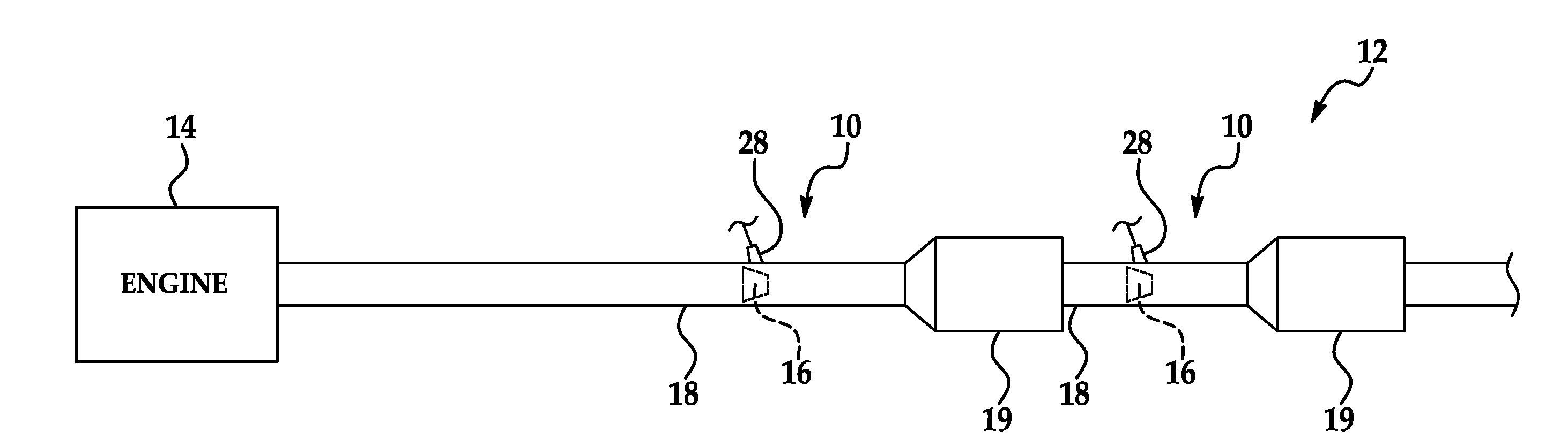
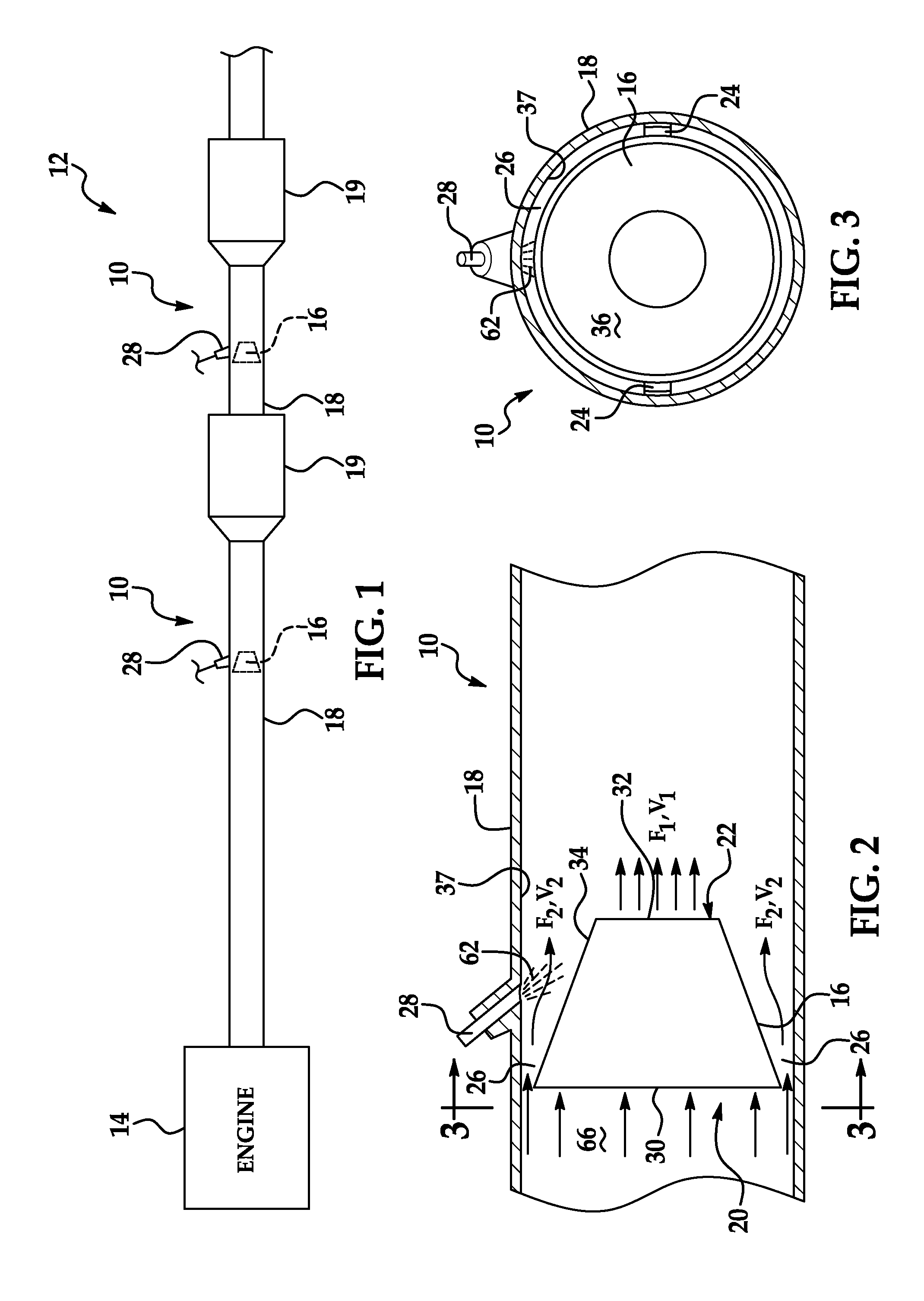
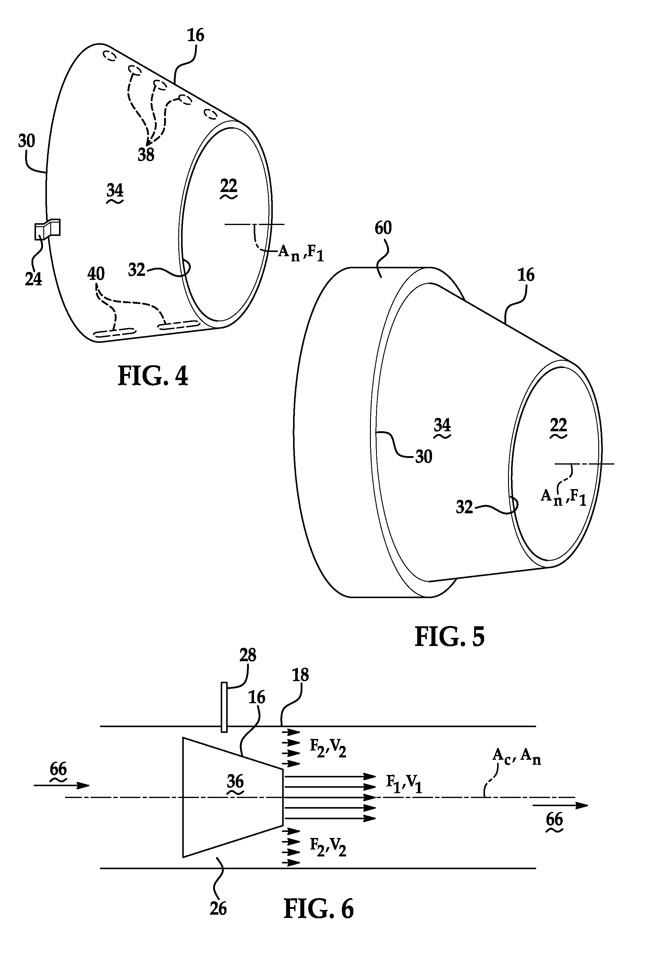
[0023]Exemplary embodiments of the present invention provide a fluid control device for mixing and evenly distributing exhaust gas, and additives thereto, across a cross-sectional area of a conduit. In one particular embodiment, the fluid control device is further configured for mixing injected fluid (e.g., gas or liquid phase), such as urea solution, hydrocarbon fuel or otherwise, with the exhaust gas such that the injected fluid is distributed across the cross-sectional area of the conduit. Advantageously, this even disbursement is particularly advantageous for exhaust treatment devices such as selective catalyst reduction (SCR) device, diesel oxidation catalyst (DOC), diesel particulate filter (DPF) or otherwise. Due to the even distribution of exhaust gas and injected fluid the exhaust treatment device operates more efficiently as the accumulation or reaction occurs across the entire cross-sectional area of the exhaust treatment device, in a relatively uniform fashion, as compar...


PUM


Abstract

Exemplary embodiments of the present invention are directed towards an apparatus and method for control of fluid flow through a conduit of an exhaust system for an engine, particularly prior to an exhaust treatment device. In one embodiment, a fluid flow control device for receiving and guiding exhaust gas from an engine towards an exhaust gas treatment device is provided. The fluid flow control device includes a nozzle disposed within an exhaust conduit of the engine. The nozzle includes an inlet opening and an outlet opening for forming a first flow path through the nozzle. The nozzle is spaced from the exhaust conduit for forming a second flow path between the nozzle and the exhaust conduit. The fluid flow control device also includes an injector disposed adjacent the nozzle. The injector may be oriented to direct a pressurized fluid to the first or second flow path.

Description

FIELD OF THE INVENTION[0001]Exemplary embodiments of the present invention are directed towards an apparatus and method for control of a fluid flow through a conduit of an exhaust system of an engine, particularly prior to an exhaust treatment device.BACKGROUND[0002]Diesel exhaust after treatment involves the use of a selective catalyst reducer (SCR) and a diesel particulate filter (DPF) along with injection of urea-water solution and diesel fuel into the exhaust gas. The performance, durability and cost of these devices depend strongly on the evaporation and mixing of the injected fluid into the exhaust gas. The injected fluid can be a liquid, gas or a mix of both phases. Therefore, mixers are placed in the exhaust flow to maximize evaporation (if a liquid is being injected) and mixing of the injected fluid (both liquid and vapor phases) with the exhaust gas. However, certain mixers and mixing configurations, in use presently, are insufficient in the vaporization and mixing of the ...

Claims


Application Information

Patent Timeline
IPC IPC(8): F01N3/04
CPCF01N3/021F01N3/2066F01N3/36F01N13/009F01N2470/30Y02T10/20F01N2240/20Y02T10/12
Inventor RANGANATHAN, RAJ P.EL TAHRY, SHERIF H.STRAUB, ROBERT D.
Owner GM GLOBAL TECH OPERATIONS LLC
Why Eureka
Try Eureka