Flowmeter

a flowmeter and flow rate technology, applied in the field of mass flowmeters, can solve the problems of increasing the mass of the flowmeter, reducing the precision, and generating coils, and achieve the effects of enhancing the rigidity of the mounting portion, reducing the thickness, and enhancing the rigidity of the thin mounting portion

Inactive Publication Date: 2010-01-14
KEYENCE
View PDF4 Cites 32 Cited by
  • Summary
  • Abstract
  • Description
  • Claims
  • Application Information

AI Technical Summary

Benefits of technology

[0023]According to the present invention, in a flowmeter in which the coils of an oscillator and detectors are arranged between a pair of fluid pipes, a penetrating portion for arranging the coils in a penetrating state is formed in the mounting portion, so that the mounting portion can be made to have a reduced thickness while bringing the pair of fluid pipes close to each other. For this reason, the distance between the pair of fluid pipes will be smaller, thereby achieving the scale reduction of the flowmeter.
[0024]Since a reinforcing portion for enhancing the rigidity of the mounting portion thus made to have a smaller thickness is provided so as to surround the outer circumference of the fluid pipes, the rigidity of the thin mounting portion will be enhanced, whereby the vibration can be restrained, and also the natural frequency of the mounting portion will be away from that of the fluid pipes, so that the vibration separation will be easier thereby to restrain the decrease in the measurement precision.

Problems solved by technology

The coil supported in a cantilever state will be not only likely to be vibrated by external turbulence vibration, but also receive a counter force of the fluid pipe due to the production errors and the like, whereby the vibration generated in the coil will be a cause of decrease in the precision.
In order to alleviate the vibration generated in the coil, it is considered that the scale for achieving higher rigidity of the cantilever supporting portion is increased; however, increase in the scale and increase in the mass of the flowmeter are inevitable, thereby deteriorating the advantages of providing a pair of fluid pipes.
However, when the pair of fluid pipes is brought close to each other, the assembly work of fixing the magnetic substance to the fluid pipes will be difficult.

Method used


Image

  • Flowmeter
  • Flowmeter
  • Flowmeter

Examples


example 1

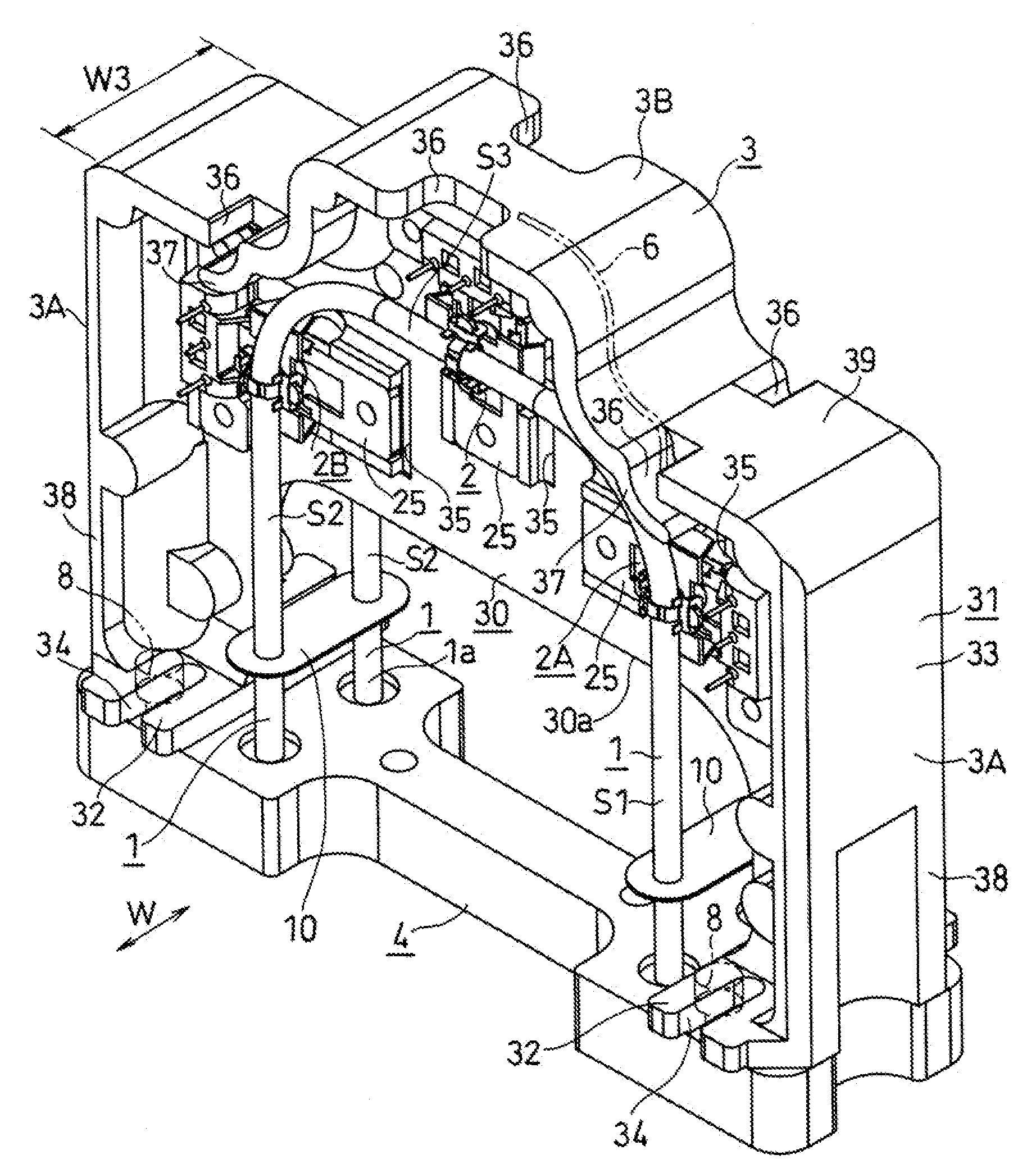
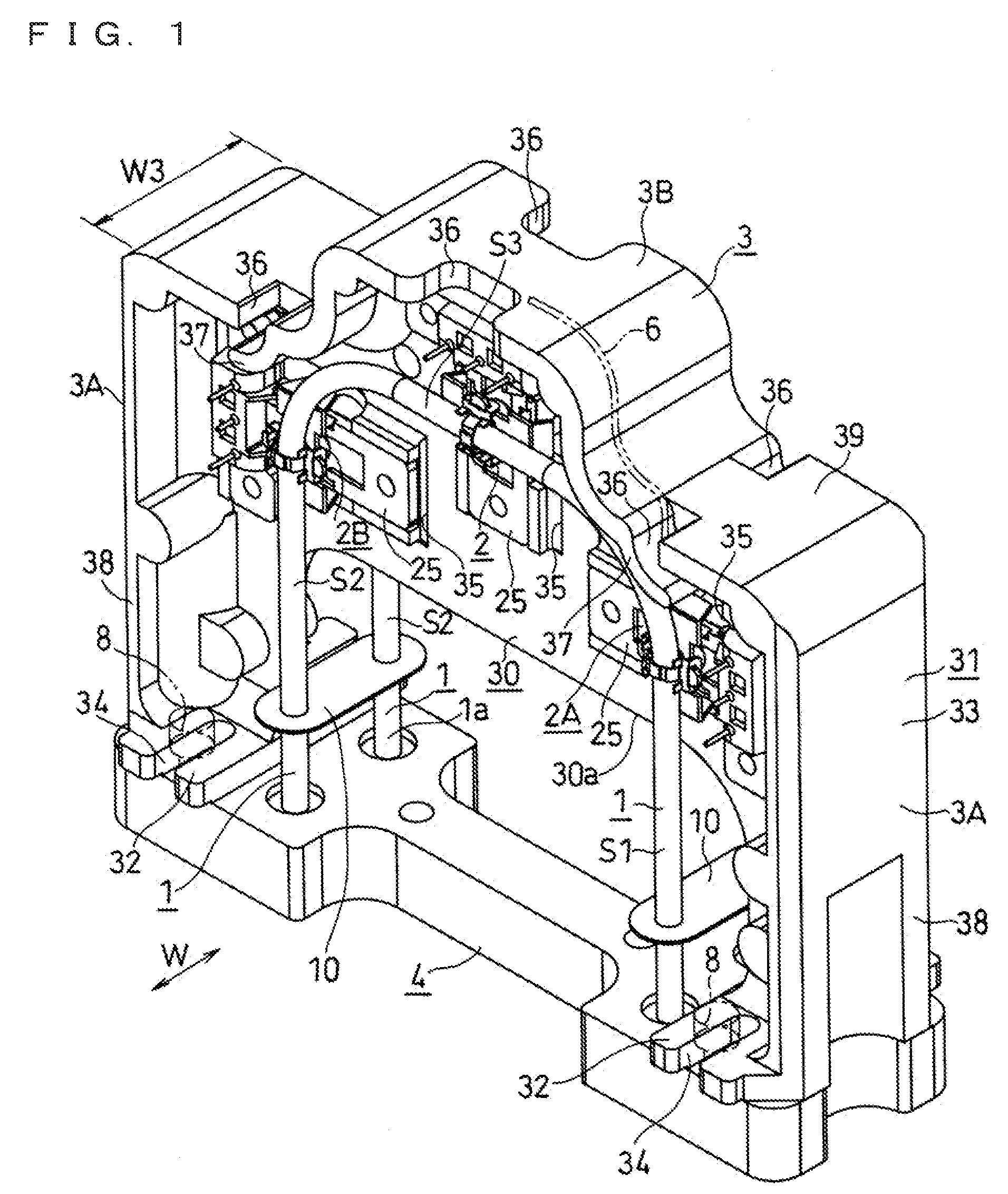
[0084]Hereafter, examples of the present invention will be described with reference to the drawings.

[0085]In the following description, the principle and the like of the flowmeter are as described in the examples of FIGS. 11 to 13 and in the above-mentioned three patent documents. In the following description, mainly the structure of the frame and the structure of mounting the coils will be described.

[0086]As shown in FIG. 1, the present flowmeter includes a pair of fluid pipes 1, a frame 3, and a supporting base 4. The frame 3 and the supporting base 4 are each made of a metal member such as aluminum or stainless steel, and the frame 3 is fixed to the supporting base 4.

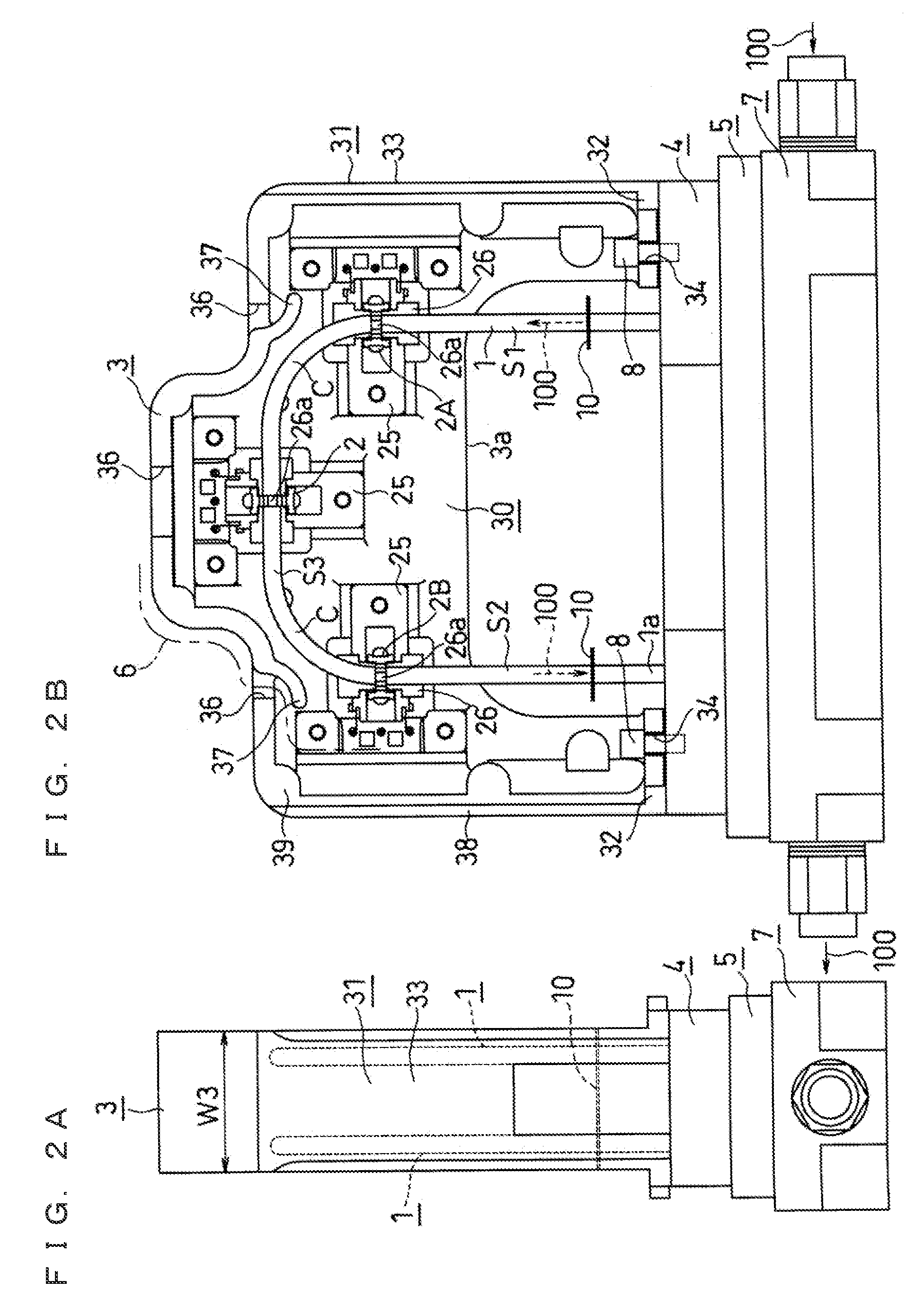
[0087]As shown in FIGS. 2A and 2B, a resin member 5 that is made of a resin having a thick plate shape and serves to weaken transmittance of vibration to the supporting base 4 is disposed on a surface of the supporting base 4 opposite to a surface to which the frame 3 is fixed.

[0088]A pipe portion 7 is disposed on a ...


PUM


Abstract

A flow meter of Coriolis type includes a supporting base that supports a pair of fluid pipes in a manner capable of being vibrated, and a frame fixed to the supporting base. The frame is integrally formed with a mounting portion disposed between the fluid pipes and having a thickness that does not interfere with the fluid pipes, a reinforcing portion disposed at the outer circumference of the mounting portion and enhancing the rigidity of the mounting portion, and a fixing portion for being fixed to the supporting base. The reinforcing portion has an outer wall portion that protrudes at least to one side of the thickness direction of the mounting portion, and substantially continuously surrounds the outer circumference of the fluid pipes. Penetrating portions for disposing the coils corresponding to respective magnetic substances mounted on the fluid pipe are formed in the mounting portion.

Description

CROSS-REFERENCE TO RELATED APPLICATIONS[0001]The present application claims foreign priority based on Japanese Patent Applications No. 2008-178635, filed Jul. 9, 2008, and No. 2008-190745, filed Jul. 24, 2008, the contents of which is incorporated herein by reference.BACKGROUND OF THE INVENTION[0002]1. Field of the Invention[0003]The present invention relates to a mass flowmeter of Coriolis type that generates a force known as Coriolis force acting in proportion to the mass flow rate of a fluid passing through a pipe by forcibly oscillating the pipe, and determining the mass flow rate by detecting a phase difference of the vibrations on the upstream side and on the downstream side of the pipe.[0004]2. Description of the Background Art[0005]A flow meter of Coriolis type forcibly oscillates with an oscillator a fluid pipe for passing a fluid to be measured, detects a phase difference of the vibrations generated on the upstream side and on the downstream side of a flow path in accordan...

Claims


Application Information

Patent Timeline
Patent Type & Authority Applications(United States)
IPC IPC(8): G01F1/84
CPCG01F1/8413G01F1/8422G01F1/8481G01F1/8472G01F1/8477G01F1/8427
Inventor SHIMIZU, ATSUSHIMAKINO, KAZUHIRO
Owner KEYENCE
Why Eureka
Try Eureka