Reflectron

Active Publication Date: 2010-01-14
CAMECA INSTR
View PDF3 Cites 8 Cited by
  • Summary
  • Abstract
  • Description
  • Claims
  • Application Information

AI Technical Summary

Benefits of technology

[0021]The front electrode may take any suitable form b

Problems solved by technology

Any residual curvature of the fields, which is difficult to avoid, leads to aberrations in ion trajectories and degradation in mass resolution.
Other embodiments (EP 0 208 894, U.S. Pat. No. 4,731,532) accomplish similar effects but with lesser operational flexibility.
Keller and Srama et al. describe reflectrons that include dual shaped grids, but images are not being resolved.
While a conventional reflectron incorporated in an atom probe can increase the measured mass resolution it has the disadvantage that an angle spread of more than approximately 8 degr

Method used


Image

  • Reflectron
  • Reflectron
  • Reflectron

Examples


Embodiment Construction

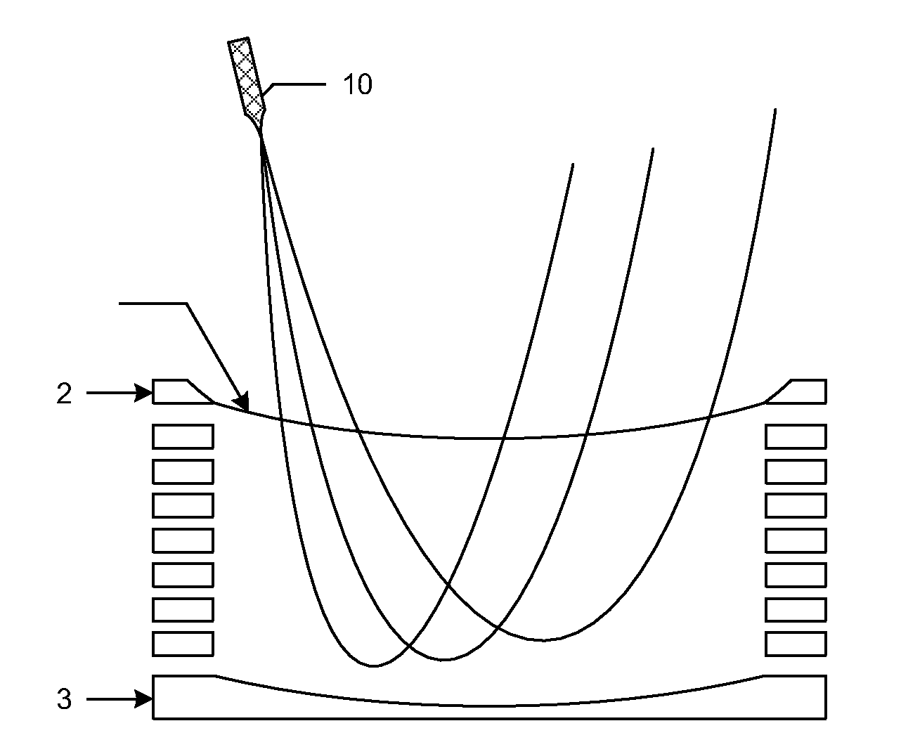
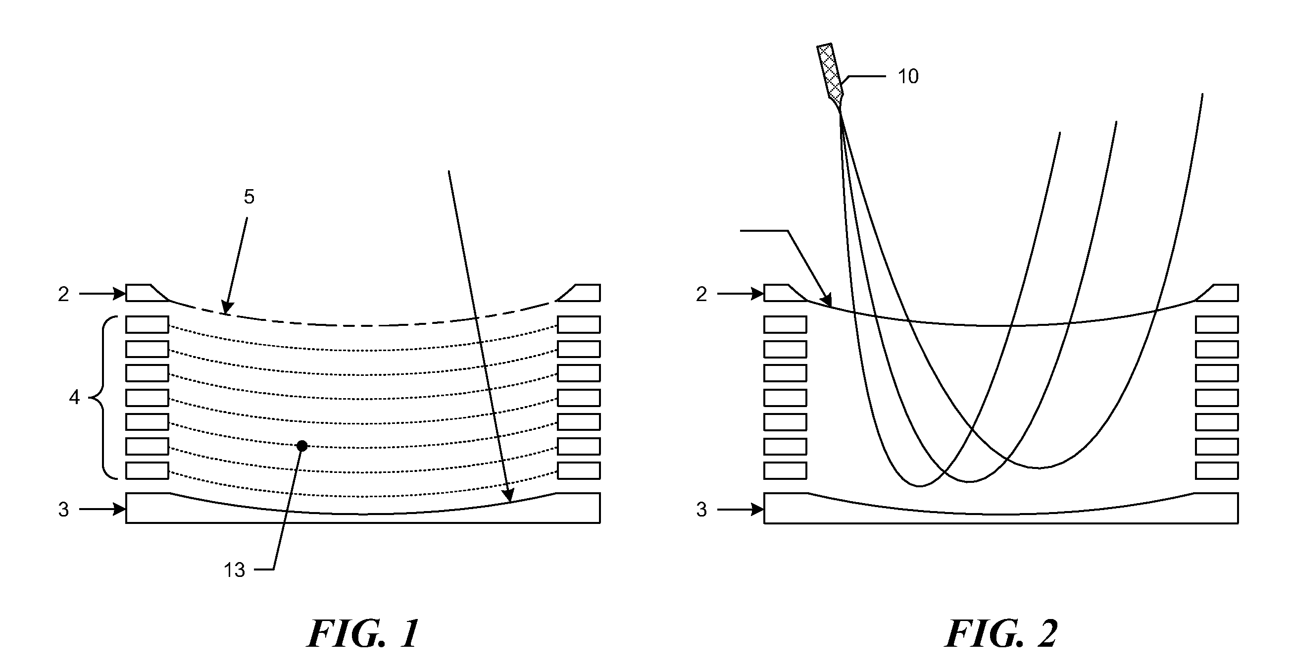
[0038]A reflectron may be incorporated as part of a three-dimensional atom probe. A three-dimensional atom probe removes individual atoms from the surface of a needle shaped specimen with a small tip radius. The atom becomes an ion and is accelerated towards a detector plate which is as large as possible, and detects a position of the ion which corresponds with the position of the atom on the specimen surface. The detector electronics measure the position at which the ion hits the detector plate and also measures the mass / charge ratio of the resulting ion by measuring the TOF of the ion from the specimen to the detector.

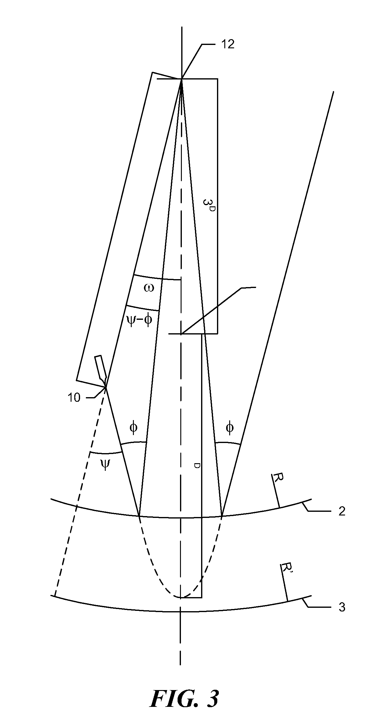
[0039]The reflectron alters the direction of the ions, by generating an electric potential greater than the energy equivalent of the ion. An ion generally enters the reflectron at an angle to a radius line of the electrodes, so that the ion travels in an elliptical path through the reflectron. The detector is offset from a path of the ions from their source to the re...


PUM


Abstract

A reflectron (1) for deflecting an ion from a specimen in a time-of-flight mass spectrometer comprises a front electrode (2) and a back electrode (3). At least one of the front and back electrodes (2, 3) is capable of generating a curved electric field. The front and back electrodes are configured to perform time focusing and resolve an image of a specimen.

Description

CROSS-REFERENCE TO RELATED APPLICATIONS[0001]The present application is a Continuation of U.S. patent application Ser. No. 11 / 913,343, filed Nov. 11, 2007, which is a U.S. National Phase of International Patent Application No. PCT / GB2006 / 001694, filed May 10, 2006, which claims the benefit of priority to both United Kingdom Patent Application No. 0509638.3, filed May 11, 2005, and U.S. Provisional Patent Application No. 60 / 682,863, filed May 20, 2005. Each of these applications is hereby incorporated by reference in their entirety.BACKGROUND[0002]The present invention relates to a reflectron for a time-of-flight mass spectrometer, and more specifically an atom probe microscope.[0003]Time-of-flight mass spectrometers typically include a specimen, a means to generate and liberate ions from the specimen and an electric field to attract these liberated ions to a detector. A means to measure the time between the initial ion liberation and the detection of the ion enables the measurement ...

Claims


Application Information

Patent Timeline
IPC IPC(8): G21K1/08H01J49/40
CPCH01J49/405
Inventor PANAYI, PETER
Owner CAMECA INSTR
Why Eureka
Try Eureka