Non-destructive test evaluation of welded claddings on rods of hydraulic cylinders used for saltwater, brackish and freshwater applications

a technology of hydraulic cylinders and claddings, which is applied in the direction of instruments, specific gravity measurement, nuclear elements, etc., can solve the problems of excessive penetration, high cost of nickel-chromium based alloys or duplex stainless steel rods, and easy corrosion

Inactive Publication Date: 2010-01-14
EATON INTELLIGENT POWER LIMITED
View PDF14 Cites 38 Cited by
  • Summary
  • Abstract
  • Description
  • Claims
  • Application Information

AI Technical Summary

Benefits of technology

[0012]Accordingly, the method and system for maintaining the rod of the hydraulic cylinder allows for the non-destructive testing or inspection of the metallic cladding on the rod to detect any discontinuities in the metallic cladding that may require repair. The metallic cladding may be inspected on-site at an offshore platform on a regular basis to monitor the wear of the metallic cladding over time and detect any discontinuities

Problems solved by technology

The hydraulic cylinders include rods, which are susceptible to corrosion caused by exposure to the elements.
However, the rods manufactured from the nickel-chromium based alloy or the duplex stainless steel are expensive.
If the metallic cladding is not properly deposited onto the rod, then the metallic cladding may include a discontinuity in the metallic cladding, i.e., a defect in the metallic cladding.
The discontinuities of the metallic cladding may include porosity in the metallic cladding, cluster porosity in the metallic cladding, cracks in the metallic cladding, shrink of the metallic cladding, incomplete fusion of the metallic cladding onto the rod, excessive penetration (high dilution) of the metallic cladding onto the rod or disbanding of the metallic cladding from the rod.
Additionally, discontinuities in the metallic cladding may form durin

Method used


Image

  • Non-destructive test evaluation of welded claddings on rods of hydraulic cylinders used for saltwater, brackish and freshwater applications
  • Non-destructive test evaluation of welded claddings on rods of hydraulic cylinders used for saltwater, brackish and freshwater applications
  • Non-destructive test evaluation of welded claddings on rods of hydraulic cylinders used for saltwater, brackish and freshwater applications

Examples


Embodiment Construction

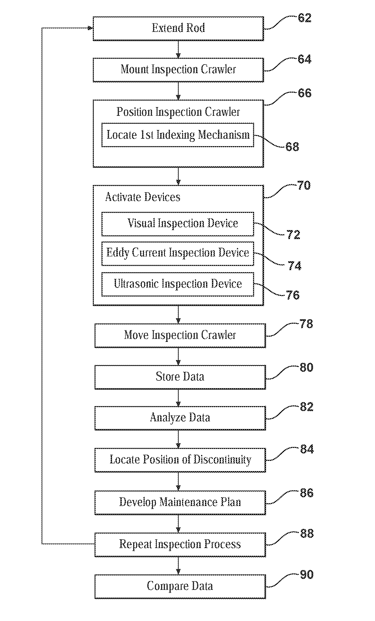
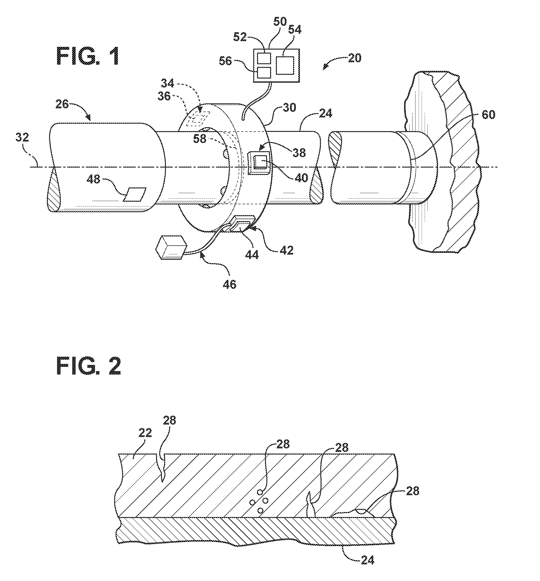
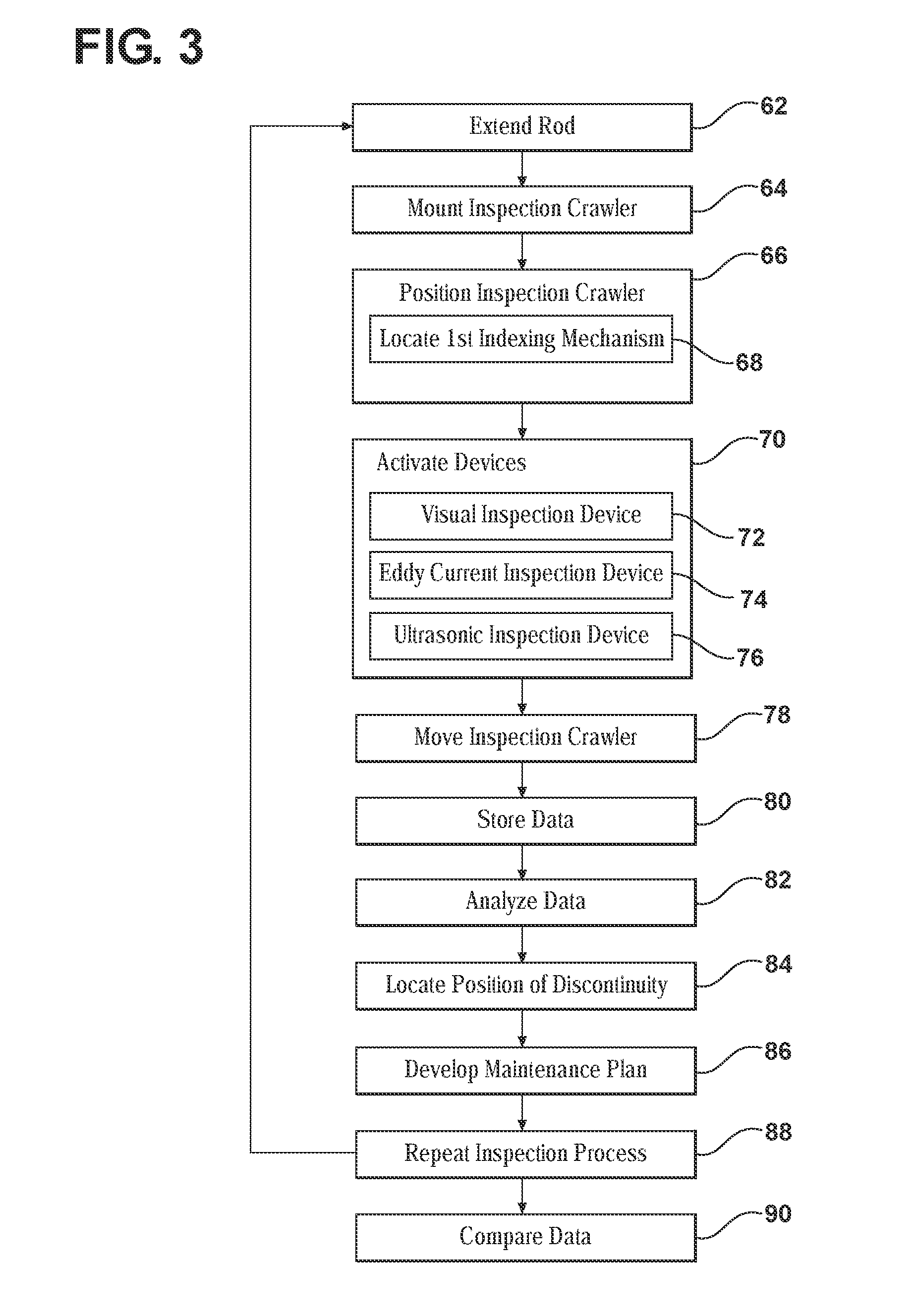
[0017]Referring to the Figures, wherein like numerals indicate like parts throughout the several views, an inspection system is shown generally at 20. The inspection system 20 is for inspecting a metallic cladding 22 on a rod 24 of a hydraulic cylinder 26. The metallic cladding 22 is shown in detail in FIG. 2. The hydraulic cylinder 26 is utilized for a motion compensation system of an offshore platform, such as an oil rig or the like. The metallic cladding 22 protects the rod 24 from the elements to prevent corrosion of the rod 24.

[0018]The rod 24 may include and be manufactured from SAE 4130 steel. However, it should be appreciated that the rod 24 may include and be manufactured from some other grade of steel, and may include and be manufactured from a metal other than steel. The protective metallic cladding 22 may include, but is not limited to, one of a stainless steel material, a nickel based material or a cobalt based material. It should be appreciated that the metallic claddi...


PUM


Abstract

A method of maintaining a rod of a hydraulic cylinder for a motion compensation system of an offshore platform includes non-destructive testing of a metallic cladding deposited onto the rod. An inspection crawler includes a visual inspection device, an eddy current inspection device and an ultrasonic inspection device. The method includes rotating the visual inspection device, the eddy current inspection device and the ultrasonic inspection device around a circumference of the rod while moving the inspection crawler along a longitudinal axis of the rod to simultaneously collect data related to the metallic cladding from the visual inspection device, the eddy current inspection device and the ultrasonic inspection device. The data is analyzed to detect any discontinuities, i.e., defects, in the metallic cladding.

Description

CROSS-REFERENCE TO RELATED APPLICATIONS[0001]This application claims the benefit of U.S. Provisional Patent Application Ser. No. 61 / 080,402, filed on Jul. 14, 2008, the disclosure of which is hereby incorporated by reference.TECHNICAL FIELD[0002]The present invention generally relates to a method of maintaining a rod of a hydraulic cylinder, and more specifically to a non-destructive method of inspecting a metallic cladding welded to a rod of the hydraulic cylinder.BACKGROUND OF THE INVENTION[0003]Offshore platforms, such as offshore oil rigs, include a motion compensation system that utilizes large hydraulic cylinders to stabilize the platforms. The hydraulic cylinders include rods, which are susceptible to corrosion caused by exposure to the elements. These large hydraulic cylinders also are used in civil engineering and hydropower applications including locks, dams and bridges.[0004]The rods of the hydraulic cylinders may include solid or tubular rods manufactured from an austeni...

Claims


Application Information

Patent Timeline
IPC IPC(8): G21C17/00
CPCG01N21/952G01N27/902G01N29/043G01N2291/2634G01N29/2412G01N29/262G01N29/265G01N29/225
Inventor KILLIAN, MICHAELAHMAD, AQUIL
Owner EATON INTELLIGENT POWER LIMITED
Why Eureka
Try Eureka