Communication Light Detecting Device

a technology of communication light and detection device, which is applied in the direction of transmission monitoring, instruments, optical elements, etc., can solve the problems of reducing work efficiency, increasing manufacturing cost, and inability to grasp the operating condition of workers such as maintenance or operation of light communication facilities, and achieves high accuracy positioning technique, simple structure, and effective extraction of communication.

Active Publication Date: 2010-01-14
HITACHI METALS LTD +2
View PDF2 Cites 43 Cited by
  • Summary
  • Abstract
  • Description
  • Claims
  • Application Information

AI Technical Summary

Benefits of technology

[0055]According to the present invention, there can be provided a communication light detecting device which permits to effectively extract a part of communication light with a simple structure that unnecessitates the highly accurate positioning technique and further permits to easily discriminate visually whether the light transmission path using invisible light is in use condition or not. Furthermore, according to the present invention, there can be provided an inexpensive communication light detecting device with a high detection sensitivity of communication light and with a high reliability in long term. Moreover, according to the present invention, there can be provided a communication light detecting device which permits to detect a failure of the communication light detecting device itself. These advantages lead to an enhancement of such as maintenance performance and operation efficiency for light transmission paths used in facilities relating to optical communication.

Problems solved by technology

For this reason, workers such as a person for maintenance or for operation of a light communication facility cannot easily grasp an operating condition whether a light transmission path in the installation is in use or not.
As a result, such problems arose that work efficiency reduces due to requirement of an extra time for grasping the operating condition of the light transmission path (for example, discrimination of in use / not in use) and an erroneous manipulation of pulling out an optical connector occurs due to erroneous recognition of a condition of the light transmission path where communication light is being transmitted, as a condition of no communication light being transmitted.
For example, the optical fiber connector disclosed in JP-A-2004-170488 possesses a problem that because the wave guide substance is provided in a very narrow gap, a highly accurate positioning technique (for example, such as adjusting length of the gap while measuring a loss of the communication light by making use of a power monitor) for the assembly is required which likely increases the manufacturing cost.
Moreover, since the light detecting substance is fluorescent substance, the light emitting time thereof is extremely short which makes the visual recognition difficult.
Also, the light signal detecting part disclosed in JP-A-2004-133071 possesses a problem that because the optical fiber in the ferrule, the optical wave guide channel substrate and the communication light output portion are required to be interconnected to match their optical axes, a highly accurate positioning technique for the assembly is required which likely increases the manufacturing cost.
Furthermore, the members such as the optical wave guide channel substrate are expensive, which causes a problem of blocking cost reduction as a whole.
The light signal monitoring device disclosed in JP-A-2003-218813 possesses a problem that since the light emitting is effected only when the light signal is reaching at the visual light converting element, the light emitting time thereof is thought extremely short which makes the visual recognition difficult.
Such as the light monitoring device and the bi-directional optical module disclosed in JP-A-2002-214487 and JP-A-2004-177549 (US 2004 / 0208458 A1) respectively possess a problem that since such as the filter and the half mirror are used for reflecting and branching the communication light, a highly accurate positioning technique for preventing reduction of the detection sensibility of the communication light caused in association with the increase of the number of parts is required, which likely increases the manufacturing cost.
In addition to the above, when the communication light detecting device itself fails, since the communication light detecting device cannot detect communication light transmitting through the light transmission path, a problem arises whether the communication light is transmitted or not, and that the information cannot be conveyed to a concerned worker.
Namely, a problem arises that the worker cannot correctly recognize the existence and absence of the communication light.

Method used


Image

  • Communication Light Detecting Device
  • Communication Light Detecting Device
  • Communication Light Detecting Device

Examples


first embodiment

of the Present Invention

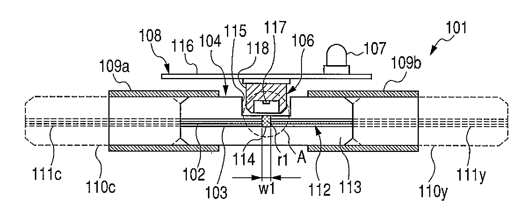
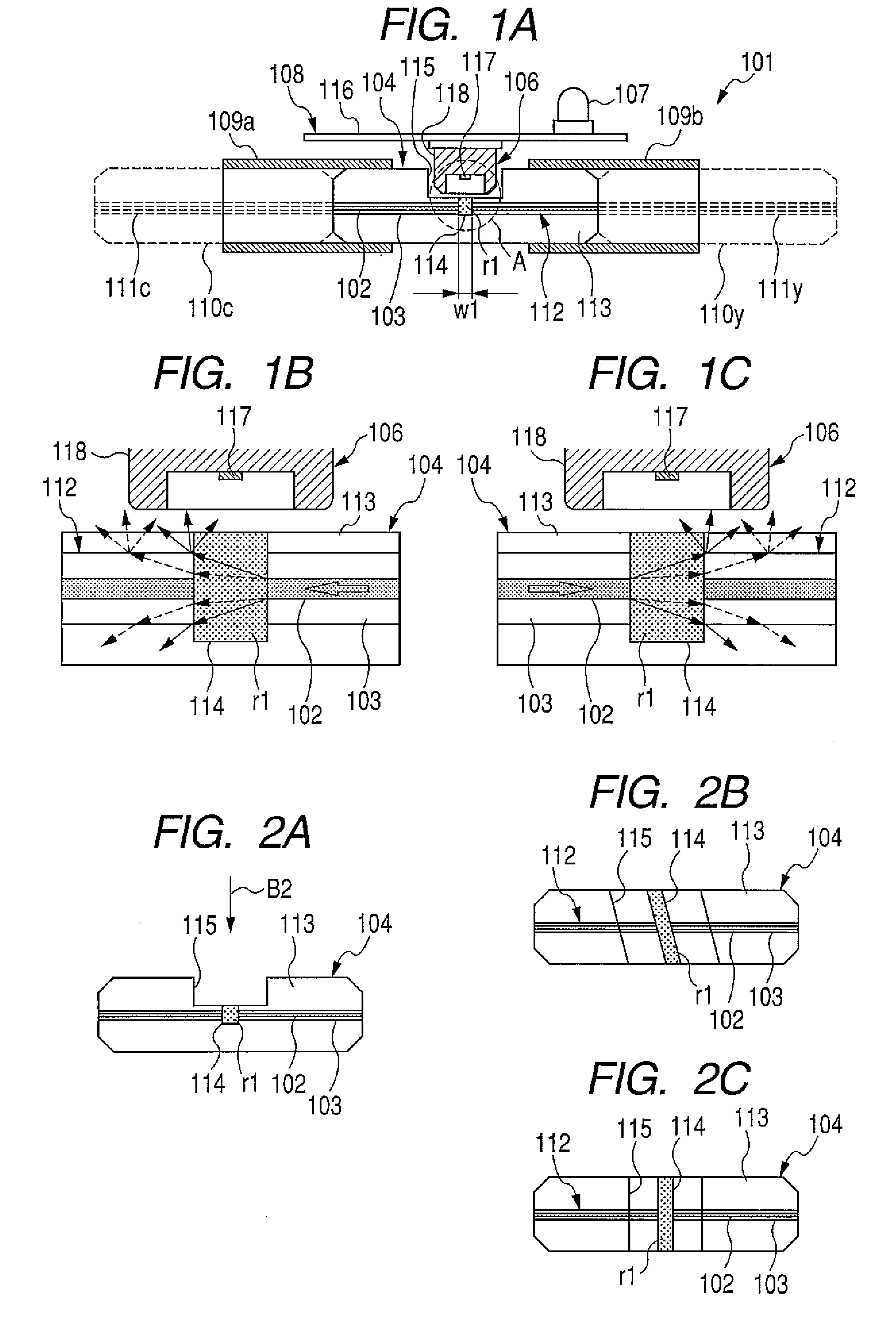
[0114]FIG. 1A is a schematic illustration showing a vertical cross sectional view along the longitudinal direction of an exemplary principal portion in a communication light detecting device according to a first embodiment. As shown in FIG. 1A, a communication light detecting device 101 is provided with: an optical coupling body 104 including a core portion 102 for photo coupling with light transmission paths and a clad portion 103; and a light detecting portion 108 collocated in parallel with and adjacent the optical coupling body 104. The light detection portion 108 includes a light receiving member 106 which receives a part of communication light propagating through the core portion 102 in the optical coupling body 104 as a leakage light and a light output member 107 that outputs a visible light when the leakage light is received by the light receiving member 106.

[0115]In more detail, the light detecting portion 108 comprises: the light receiving member 10...

second embodiment

of the Present Invention

[0146]FIG. 6 is a schematic illustration showing a vertical cross sectional view along the longitudinal direction of an exemplary principal portion in a communication light detecting device according to a second embodiment. Although in the communication light detecting device 101 according to the first embodiment, the optical coupling body 104 in which the container groove 115 is formed in the ferrule 113 is used and a part of the light receiving member 106 is accommodated in the container groove 115, as in the communication light detecting device 201 according to the second embodiment, as shown in FIG. 6, by using an optical coupling body 204 in which no container groove for taking in a part of the light receiving member 106 is formed, the light receiving member 106 can be collocated so as to be adjacent the ferrule 113 of the optical coupling body 204. The communication light detecting device 201 according to the second embodiment achieves the like function...

third embodiment

of the Present Invention

[0147]FIG. 7 is a schematic illustration showing a vertical cross sectional view along the longitudinal direction of an example of only an optical coupling body in a communication light detecting device according to a third embodiment. Although in the communication light detecting device 101 according to the first embodiment, the optical coupling body 104 in which the light detecting use groove 114 having a substantially rectangular shape seen when the optical coupling body is vertically cross sectioned along the longitudinal direction is used, as an optical coupling body 304 in the communication light detecting device according to the third embodiment, as shown in FIG. 7, the optical coupling body 304 in which the light detecting use groove 314 having a substantially V shape seen when the optical coupling body 304 is vertically cross sectioned along the longitudinal direction can be used. The communication light detecting device according to the third embodi...


PUM


Abstract

A communication light detecting device interconnecting light transmission paths and collocated therebetween, comprises: an optical coupling body including a core portion for photo coupling with the light transmission paths, and a light extracting portion for extracting a part of the communication light as a leakage light; and a light detecting portion having a light receiving member for receiving the leakage light. The light extracting portion is preferable to possess a lower refractive index than that of the core portion. Besides, the light extracting portion is preferable to include a light detecting use groove with a groove width of 50 μm or more and 140 μm or less formed by cutting and separating the core portion. Besides, the light extracting portion is preferable to be the optical coupling body in which outer diameter of the core portion is different from the outer diameter of a core of the light transmission path.

Description

CLAIM OF PRIORITY[0001]The present application claims priority from Japanese patent applications: serial no. 2008-128799 filed on May 15, 2008; serial no. 2008-128800 filed on May 15, 2008; serial no. 2009-080104 filed on Mar. 27, 2009; and serial no. 2009-080105 filed on Mar. 27, 2009, the contents of which are hereby incorporated by reference into this application.BACKGROUND OF THE INVENTION[0002]1. Field of the Invention[0003]The present invention relates to a communication light detecting device provided at a portion where light transmission paths are interconnected and, in particular, relates to a communication light detecting device which is able to confirm the communication state in the transmission paths. Further, the present invention relates to a communication light detecting device provided at a portion where light transmission paths are interconnected and, in particular, relates to a communication light detecting device which is able to detect a failure of the a communic...

Claims


Application Information

Patent Timeline
Patent Type & Authority Applications(United States)
IPC IPC(8): H04B10/12
CPCG02B6/4219G02B6/4201G02B6/4286G02B6/424G02B6/429G02B6/4259
Inventor KOJIMA, SEIJISUZUKI, KANAKONAKATANI, YOSHIHIROISHIKAWA, TOSHIHIKONISHIKAWA, TAKAOITO, KOJIROSUEOKA, TETSUYA
Owner HITACHI METALS LTD
Why Eureka
Try Eureka