Insulation displacement contact and contacting device

a technology of displacement contact and contacting device, which is applied in the direction of contact members penetrating/cutting insulation/cable strands, electrical apparatus, fastening/insulating connecting parts, etc., can solve the problems of large installation height, large material strength assumption, and already limited degree of re-usability. , to achieve the effect of reversing reliable and comparatively economical manufacturing methods

Inactive Publication Date: 2010-01-14
REICHLE & DE-MASSARI
View PDF17 Cites 17 Cited by
  • Summary
  • Abstract
  • Description
  • Claims
  • Application Information

AI Technical Summary

Benefits of technology

[0031]Preferably, the insulation displacement contact is designed such that a through-running conductor can be contacted, without needing to be snapped off or even cut. In particular, a conductor that is to be contacted should preferably be contacted substantially (under application of a force) only by the contact blades of the insulation displacement contact; the fork sections can thereby be optimally formed for their function as elastic springs.
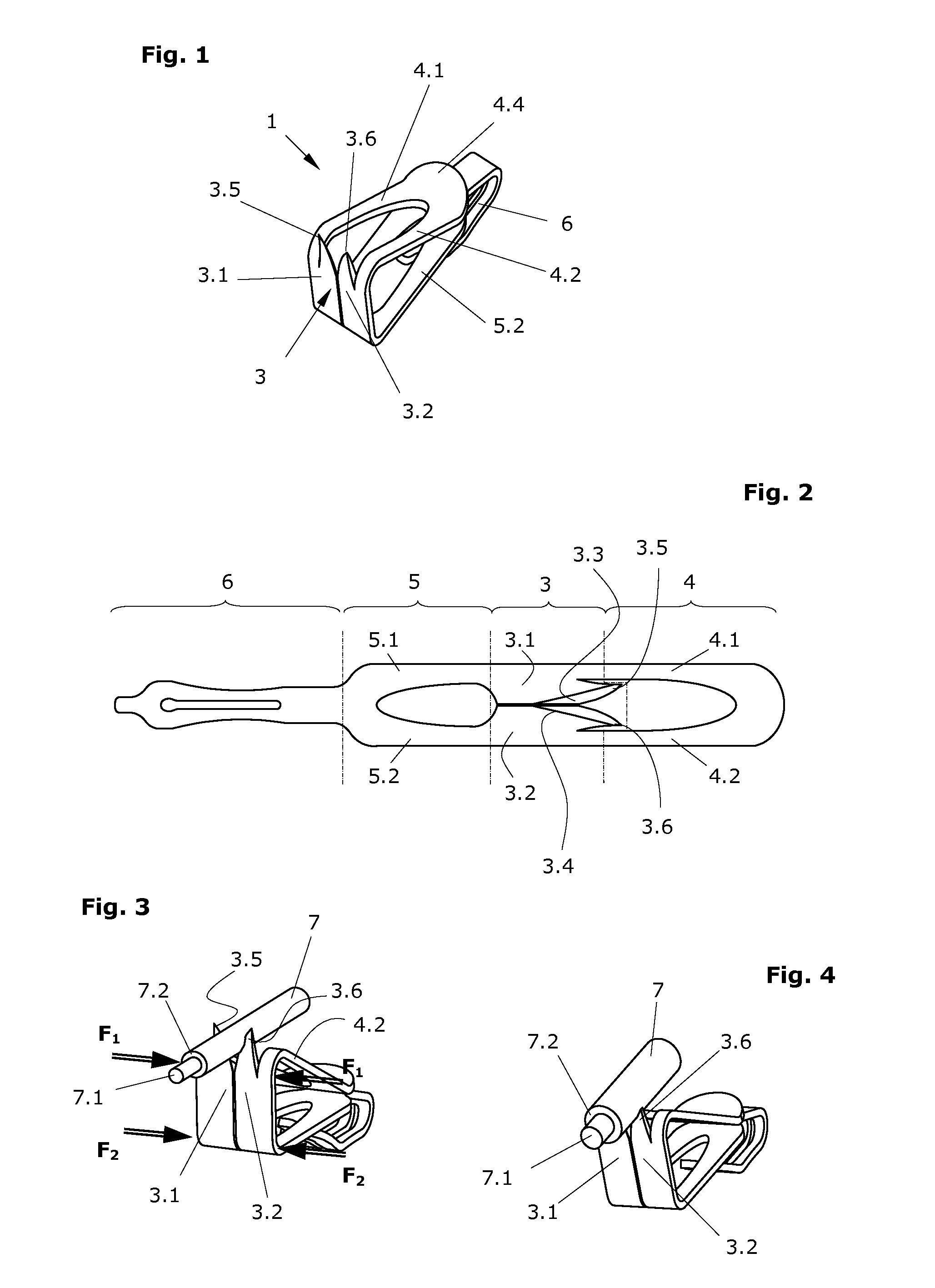
[0032]According to a particularly preferred embodiment, one of the two fork sections is angled at more than 90°, while the other is angled to approximately 90°. The first, more than 90° angled fork section therein corresponds to the first section, which adjoins the proximal end of the cutter section (i.e. the “upper” fork section). In this preferred embodiment, the wiring of a through-running conductor is possible; the fork bridges of the two fork sections both run “underneath” the conductor.
[0033]In a first variant the first and second fork sections are angled to the cutter section such that they, relative to a cutter-section plane, lie on the same side of the cutter section. This configuration makes it possible that without additional requirement of space the first fork section must only be angled to a few degrees more than 90°—e.g. to about 100-140°. This achieves a particularly advantageous unstressed force distribution and makes possible the use of blades that are themselves rigid. The configuration is also advantageous with respect to the dimensioning, such that comparatively large first and second forks can nevertheless be used, wherein as the fork size is increased, the insulation displacement contact as a whole only increases in size in one direction.
[0034]In a second variant, the first and second fork sections lie on different sides of the cutter section plane. This variant is especially advantageous if the first fork section is angled at 180° or at anot

Problems solved by technology

In addition, they require a sizeable installation height and in most embodiments can only create a contact from one conductor to one other.
Moreover, in general they are only appropriate for a single wiring of a conductor or at most only a very few wiring procedures, since they may be considerably plastically deformed when the cable strand is inserted between the blades.
The extent of the plastic deformation depends in many cases upon how deeply the cable strand, and with it the conductor, is inserted between the blades of the IDC, so that the already limited degree of re-usability is also an unpredictable value.
However, it is disadvantageous that in this design a larger material strength is assumed, or the contact strength is relatively limited in relation to the overall size, and that the spring force is given by the thickness of the plate, and thus is a parameter that can

Method used


Image

  • Insulation displacement contact and contacting device
  • Insulation displacement contact and contacting device
  • Insulation displacement contact and contacting device

Examples


Embodiment Construction

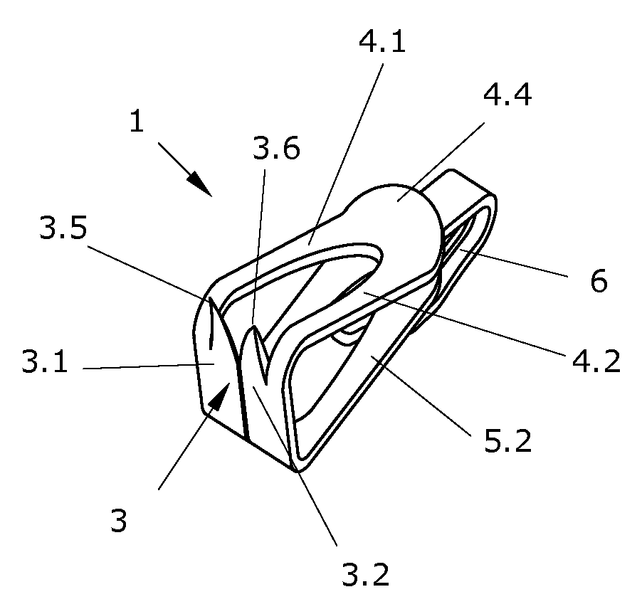
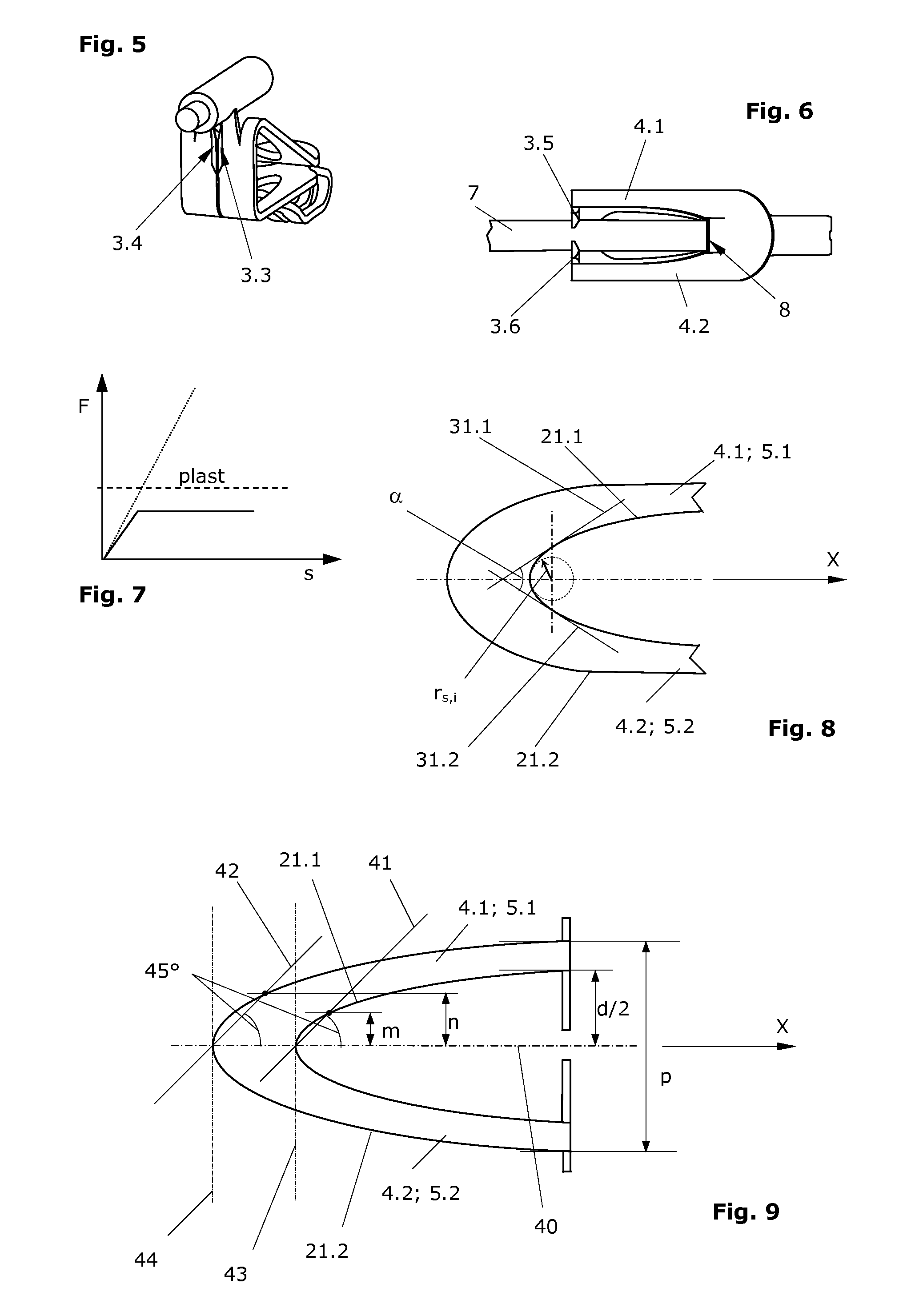
[0055]The depictions of FIGS. 2 and 15 correspond to the insulation displacement contacts that are shown in FIGS. 1 and respectively 13 / 14 in the flat form of a blank, as they exist for example as semi-finished products before being bent into the desired 3-D form; in FIGS. 2 and 15 the bending lines (in reality they are regions around these lines) are respectively also depicted, which define the transition between the cutter section on the one side and the fork sections on the other sides.

[0056]The insulation displacement contact 1 depicted in FIGS. 1-4 comprises a cutter section 3 with two blades 3.1, 3.2. In an area of the blades, there are opposing cutting edges 3.3, 3.4 which are designed to cut through an insulation 7.2 of a conductor 7.1. In this text, “blades” will indicate whole length of the elements that make up the cutter section, thus not only in the area in which the cutting edges exist.

[0057]A first fork 4 with two fork prongs 4.1, 4.2 connects on the proximal side (in...


PUM


Abstract

An insulation displacement contact (1) according to the invention essentially distinguishes itself in that as a whole it comprises a cutter section with two opposing contact blades (3.1, 3.2) together with two fork sections which contribute to a clamping force with which the two contact blades are pressed together as soon as a conductor is inserted between the contact blades and they are pushed away from one another. In the process one fork (4) exerts proximally (i.e. on the side, from which the conductor is inserted) and the other fork (5) distally (i.e. on the side opposite), such that the two contact blades are pushed together at four points. The fork sections are angled relative to the cutter section (3), i.e. they do not run in the same plane as the cutter section. The two fork sections each constitute an independent, elastic spring. This means that in they will be substantially elastically and not plastically deformed as a result of the moving-apart of the contact blades (3.1, 3.2) to the thickness of a conductor to be contacted.

Description

BACKGROUND OF THE INVENTION[0001]1. Field of the Invention[0002]The invention relates to the electrical contacting of insulated conductors by means of an insulation displacement contact. In particular, the invention relates to an insulation displacement contact and a contacting device with an insulation displacement contact.[0003]2. Description of Related Art[0004]For the electrical contacting of cable strands (insulated stranded cable conductors or wires), electrically conductive terminals are often used, which can be clamped onto and form an electrical contact with a contacting region of the conductor, which has been de-insulated in a previous step. In addition to these, insulation-piercing technologies are well known. These have to do with electrically conductive contacting elements, which are designed such that they can break through the electrical insulation at the contacting site and contact the underlying conductor without prior de-insulation. The best-known in this regard ar...

Claims


Application Information

Patent Timeline
IPC IPC(8): H01R4/24
CPCH01R4/2462
Inventor GYAGANG, TENSINGGROSSKOPF, REIMAR
Owner REICHLE & DE-MASSARI
Why Eureka
Try Eureka