
Ultrasound emitting system and ultrasound treatment machine comprising said system

a technology of ultrasound and emitting system, which is applied in the field of ultrasonic emission system, can solve the problems of system danger, system damage, and fragile materials when subjected to ultrasound, and achieve the effect of reducing the power supply voltage of the ultrasound emission system

Inactive Publication Date: 2010-01-14
CORNEAL INNOVATION
View PDF7 Cites 12 Cited by
  • Summary
  • Abstract
  • Description
  • Claims
  • Application Information

AI Technical Summary

Benefits of technology

[0015]The object of the invention is to remedy the above-mentioned drawback by enabling the power supply voltage of the ultrasound emission system to be reduced.
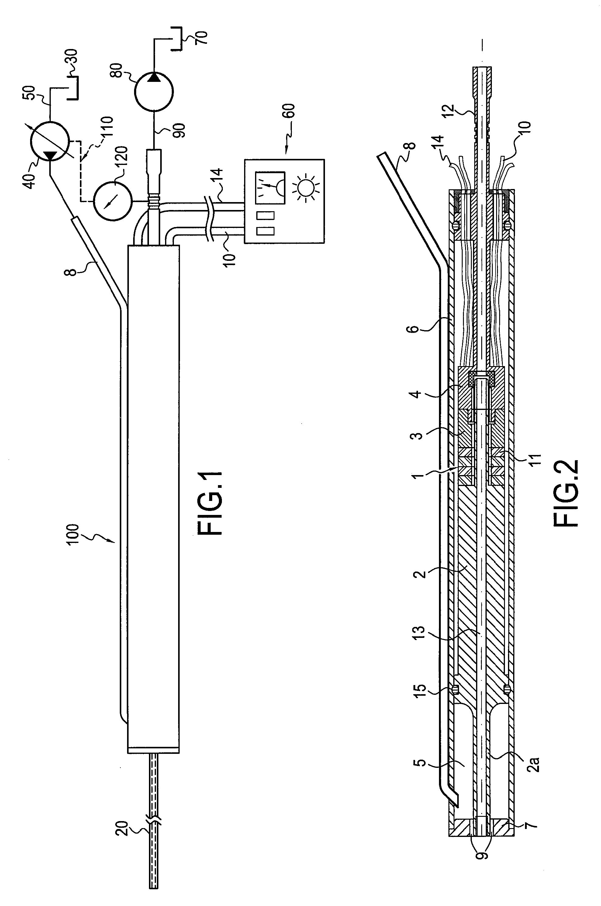
[0017]The piezoelectric assembly is preferably powered over a frequency range close to a resonant frequency for the vibrating parts, i.e. the piezoelectric assembly, the sonotrode, and the hand-piece, which frequency thus also depends on the housing and on the cannula. Operating in such a frequency range enables the conversion of electrical power into mechanical power to be performed efficiently.
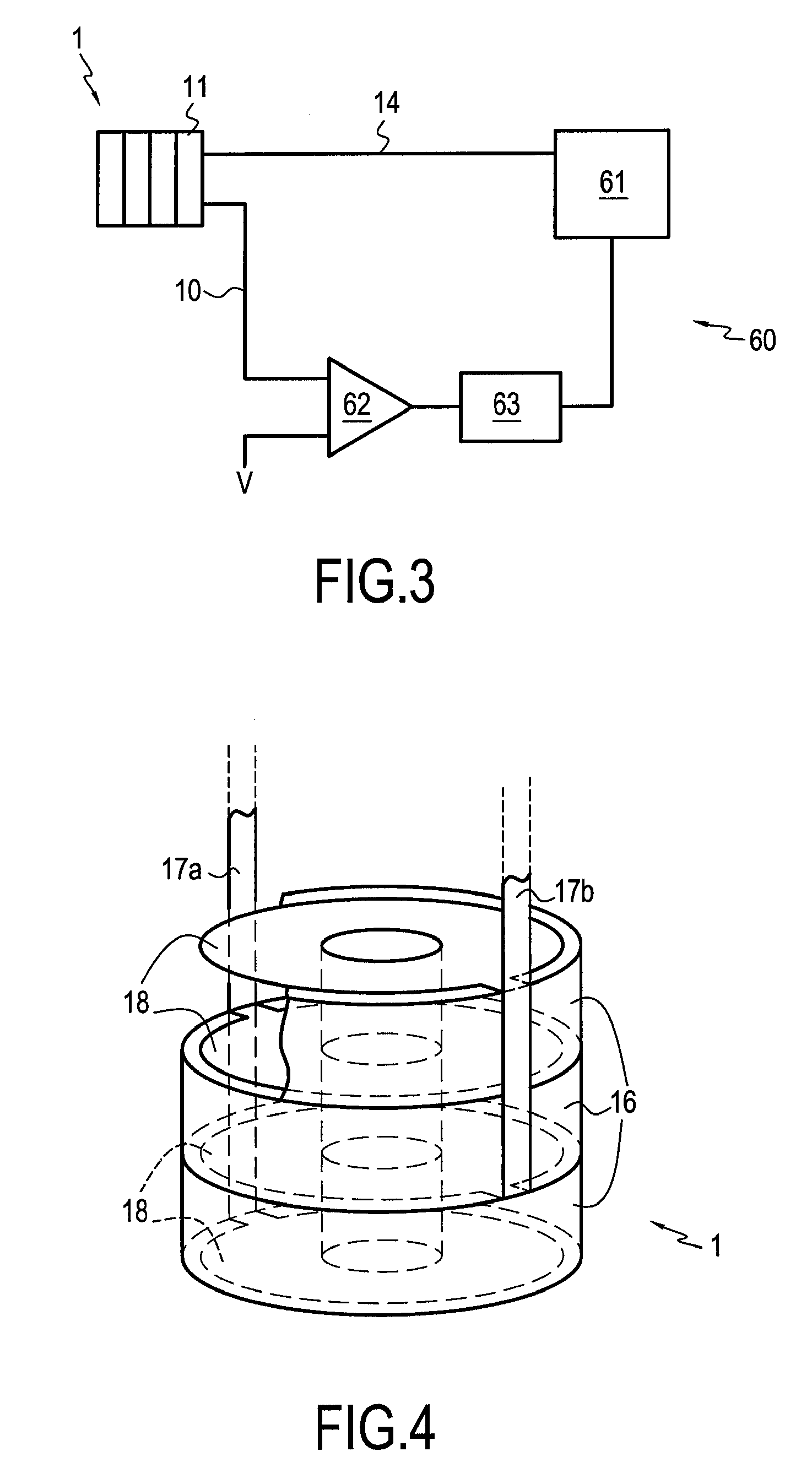
[0020]The use of such a stack of piezoelectric layers makes it possible to limit the power supply voltage to an alternating voltage lying in the range 1 Vrms to 50 Vrms. Thus, the system presents low electrical risk and may be classified in the “very low voltage” category using the above-mentioned terminology.
[0024]By modulating the excitation frequency of the piezoelectric assembly, it is possible, depending on the intended effect, either to increase the amplitude of the vibration by coming closer to the resonant frequency of the elements coupled in vibration within the system, or to reduce the amplitude by moving away from that frequency.

Problems solved by technology

Materials that are fragile when subjected to ultrasound are then emulsified (destroyed and fragmented).
Such a system thus presents a potential danger in the event of malfunction or degradation of the isolation, and it needs to be handled with care.

Method used


Image

  • Ultrasound emitting system and ultrasound treatment machine comprising said system
  • Ultrasound emitting system and ultrasound treatment machine comprising said system
  • Ultrasound emitting system and ultrasound treatment machine comprising said system

Examples


Embodiment Construction

[0032]The description below of a preferred embodiment of the invention relates to a phacoemulsification hand-piece incorporating an ultrasound emission system of the invention. Nevertheless, such an ultrasound emission system can clearly be used for other applications and in other types of machine.

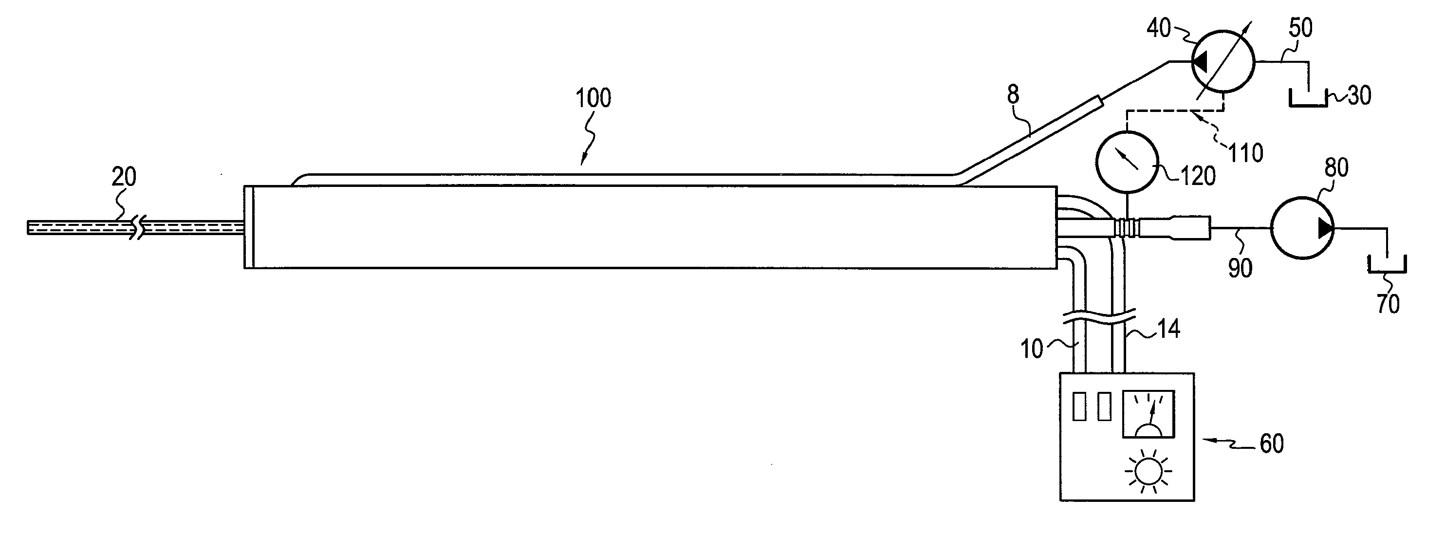
[0033]With reference to FIG. 1, there follows a description of an ultrasound treatment machine of the invention. It comprises a cannula 20, an ultrasound emission system 100; and for fluid feed: a tank 30, a pump 40, and a pipe 50; for fluid removal: a tank 70, a pump 80, and a pipe 90; electrical power supply and control means 60; and a device 110 for controlling the pump 40 and making use of a pressure gauge 120.

[0034]The cannula 20 is fastened to the front end of the ultrasound emission system 100. It comprises an outer cylindrical sheath for injecting fluid towards the surface that is to be cleaned, and an inner cylindrical needle for sucking up fluid from said surface.

[0035]The fluid ...


PUM


Abstract

An ultrasound emission system comprising a substantially cylindrical body and, inside said body: a piezoelectric assembly for producing ultrasound along the axial direction of said body, a sonotrode assembly, a prestress ring, and further comprising electrical power supply and control means; said piezoelectric assembly being constituted by a stack of layers of piezoelectric material, each layer being provided with excitation electrodes and presenting thickness lying in the range 20 μm to 100 μm. The system, generally fitted with a cannula enabling the ultrasound treatment to be applied to a determined area, can itself be incorporated in such a manner as to make an ultrasound treatment machine serving in particular to perform phacoemulsification.

Description

[0001]This is a 371 national phase application of PCT / FR2007 / 052035 filed 27 Sep. 2007, claiming priority to French Patent Application No. 06 / 53965 filed 27 Sep. 2006, the contents of which are incorporated herein by reference.BACKGROUND OF THE INVENTION[0002]The present invention relates to an ultrasound emission system. Such a system may be incorporated in an ultrasound or other treatment machine for treating a surface, by using ultrasound to destroy and remove fragile material, in particular certain kinds of biological tissue. One known application consists in incorporating such a system in a phacoemulsification machine. Such a machine can be used for performing a cataract operation. This operation consists in acting on the lens of an eye, once the lens has become opaque and therefore needs to be destroyed, so it can be replaced by an artificial lens that is transparent. The phacoemulsification machine enables the lens to be destroyed by ultrasound and enables the debris thereof ...

Claims


Application Information

Patent Timeline
IPC IPC(8): A61N7/00
CPCB06B1/0611
Inventor GAGNEPAIN, CEDRICANDRE, JEAN-MARC
Owner CORNEAL INNOVATION
Learn More