Guidewire and catheter management device
- Summary
- Abstract
- Description
- Claims
- Application Information
AI Technical Summary
Benefits of technology
Problems solved by technology
Method used
Image
Examples
first embodiment
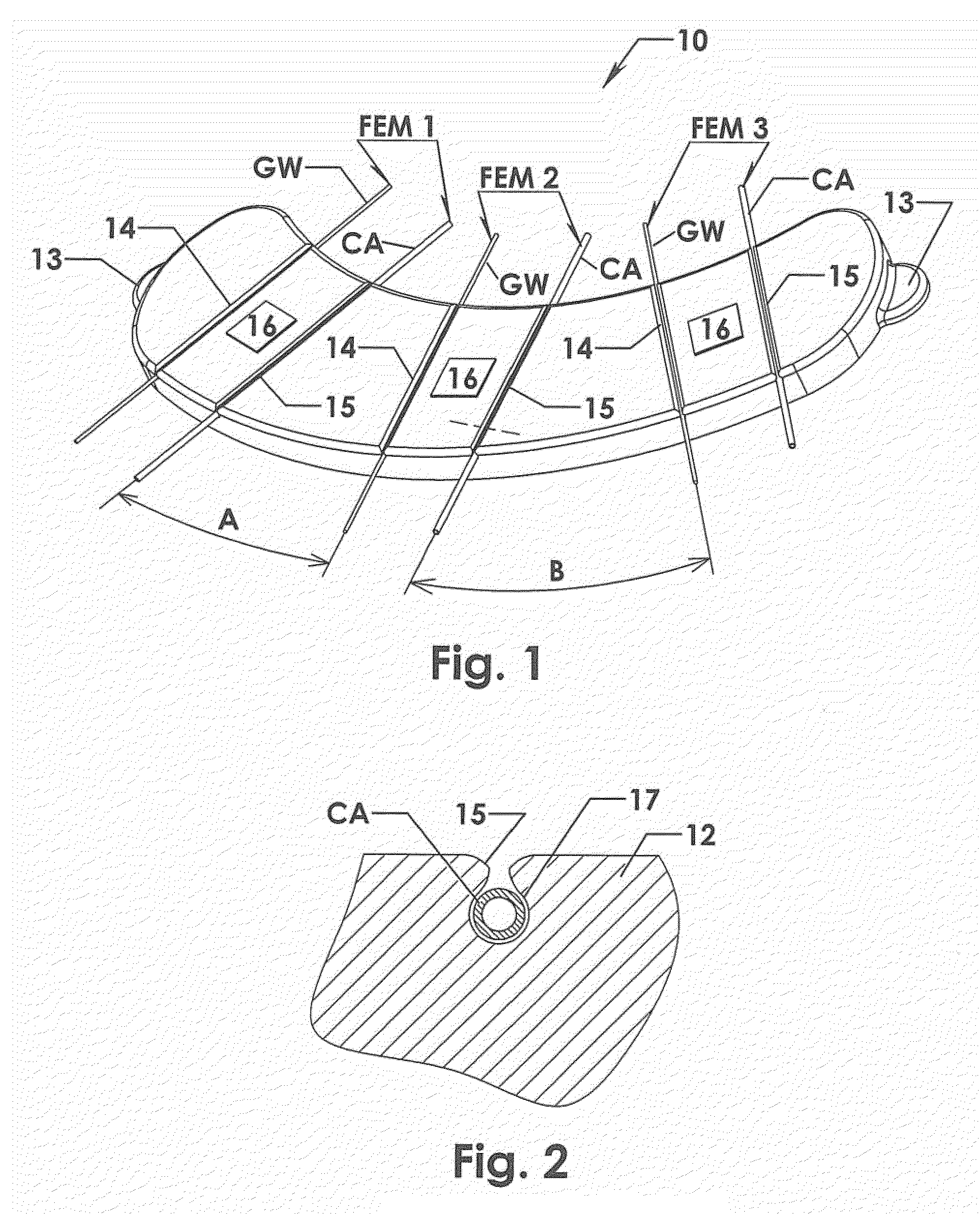
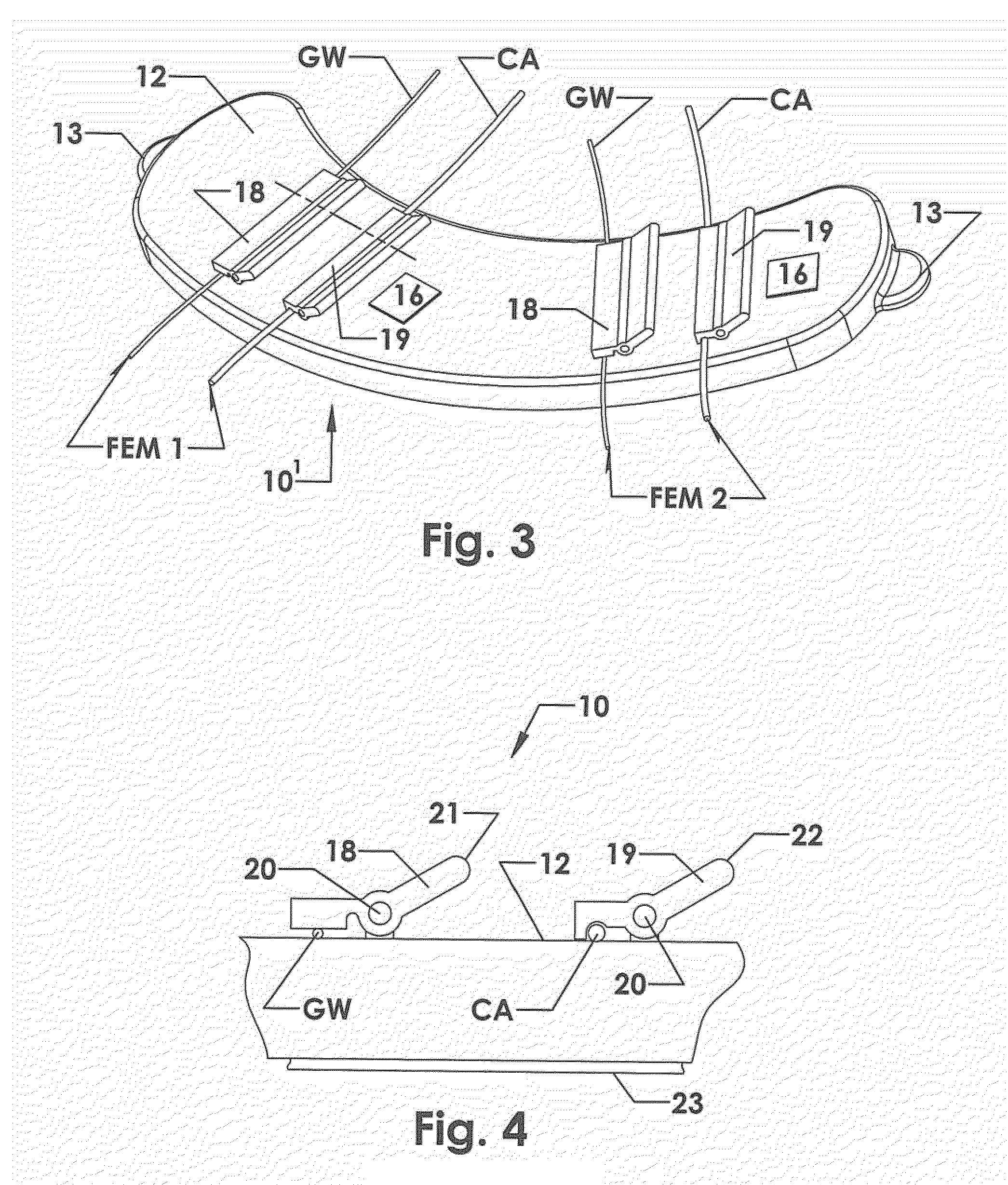
[0036]As shown in FIG. 1, the device 10 of the present invention includes a pad 12 with a plurality of pairs of grooves 14, 15 in its upper surface. Alternatively, the grooves 14, 15 could be formed in a body of flexible material that is mounted on the pad 12. The pad 12 is constructed of a firm but flexible material. Two or more flat tabs 13 can be formed on the pad 12, to provide surfaces to which surgical clamps can be attached, to hold the pad 12 on a surgical drape, in a selected position and orientation relative to a Y adaptor. Each pair of grooves 14, 15 has an associated label 16, identifying the guidewire GW and the catheter CA that are secured in the respective groove pair. A first pair of flexible elongated members FEM1 can be secured in a first pair of grooves 14, 15, near one end of the pad 12, with a guidewire GW in a first groove 14 and a catheter CA in a second groove 15. Similarly, a second pair of flexible elongated members FEM2 can be secured in a second pair of g...
fifth embodiment
[0066]In this fifth embodiment, the device 60 has a housing 61 with a top surface 48 from which extend vertically upward a number of supports 54a, 54b, etc. A number of retaining member housings 44a -44c are illustrated as mounted in the housing 61. A number of retaining members 46a-46f are illustrated mounted in the retaining member housings. In many cases, the retaining member housings may be formed integrally with the housing 61. As shown in FIG. 7(C), the retaining members 46i may be inserted into the retaining member housings via snap-fit components 47 (shown in FIG. 7(F)). Also as shown in FIG. 7(F), the retaining members may be formed using the open mold process described above in connection with FIG. 5(E), with the benefits appertaining thereto. FIG. 7(F) also illustrates details of the slot and groove which are generally the same as described above in connection with FIGS. 6(C)-6(E), are given corresponding (and primed) reference numerals, and are thus not further described...
sixth embodiment
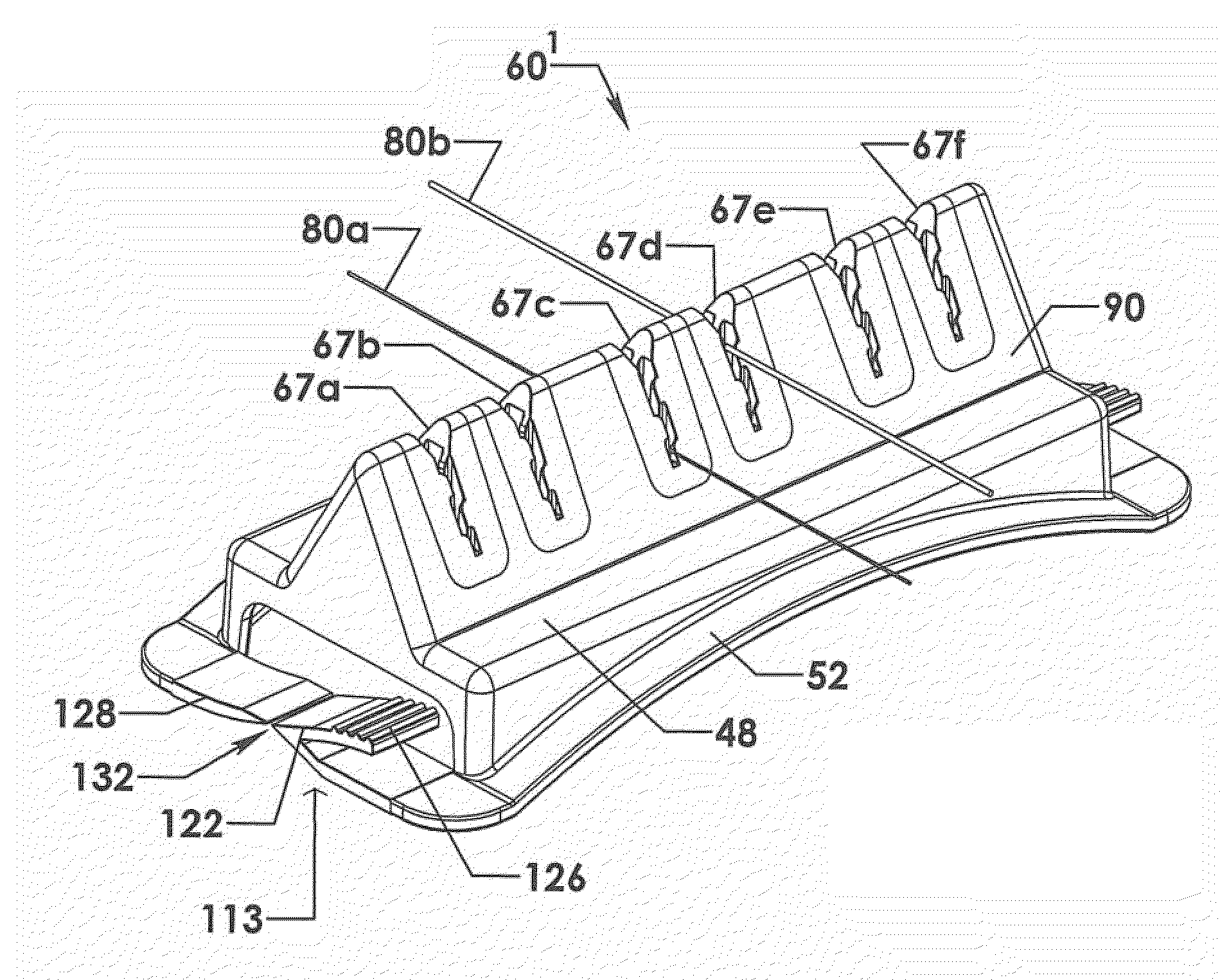
[0067]FIGS. 8(A)-8(E) illustrate a number of views of a device 60′ for catheter and guidewire management, having a housing 90 with vertical supports 91a-91g. In this device 60′, retaining members 67a-67f with ribbed slots or grooves are employed. Certain elements are similar to those described above with respect to FIGS. 6(A)-6(E), and these elements have been given the same reference numerals and are not further described here.
[0068]Details of the ribbed retaining members 67i are shown in FIGS. 8(E)-8(G). The retaining member 67i includes fingers 72a and 72b. The finger 72a includes a rib 74a and an indentation 76a, while the finger 72b is shown with a rib 74b and an indentation 76b. The rib 74a fits into the indentation 76b while the rib 74b fits into the indentation 76a. In this way, a catheter or guidewire may be held even more securely, while minimizing the effects of “healing”, described in greater detail below. Such retaining members 67i may be conveniently manufactured using...
PUM
| Property | Measurement | Unit |
|---|---|---|
| Angle | aaaaa | aaaaa |
| Angle | aaaaa | aaaaa |
| Angle | aaaaa | aaaaa |
Abstract
Description
Claims
Application Information
 - R&D
- Intellectual Property
- Life Sciences
- Materials
- Tech Scout
- Unparalleled Data Quality
- Higher Quality Content
- 60% Fewer Hallucinations
Browse by: Latest US Patents, China's latest patents, Technical Efficacy Thesaurus, Application Domain, Technology Topic, Popular Technical Reports.
© 2025 PatSnap. All rights reserved.Legal|Privacy policy|Modern Slavery Act Transparency Statement|Sitemap|About US| Contact US: help@patsnap.com


