
Apparatus and method for ram bending of tube material

a technology of ram bending and tube material, which is applied in the field of ram bending apparatus and tube material bending method, can solve the problems of increasing cycle time, increasing the number of dies, and increasing the number of dies, and achieves the effect of high productivity

Active Publication Date: 2010-01-21
NIPPON STEEL CORP
View PDF11 Cites 6 Cited by
  • Summary
  • Abstract
  • Description
  • Claims
  • Application Information

AI Technical Summary

Benefits of technology

[0007]As described above, in the existing apparatuses and methods for bending a tube material, it was not possible to achieve the three characteristics of bending by a large bending radius without requiring large scale facilities or dies, bending resistant to wrinkling and buckling at the inner side of the bending, and bending with a high productivity. Therefore, the present invention has its object to provide a new bending apparatus and bending method of a tube material enabling these three characteristics to be obtained simultaneously.

Problems solved by technology

However, put another way, when performing one type of bending, there is the disadvantage that many dies become necessary.
Further, bending by a small bending radius is a strong point, but when bending by a large bending radius, a large rotary bending die becomes necessary.
To avoid enlargement of the apparatus, by practice has sometimes been to performing bending by a small bending radius and linear shaping repeatedly to make the overall result close to that of bending by a large bending radius, but this means a plurality of bending operations, so the cycle time becomes longer and the productivity is therefore no good.
Further, there are the drawbacks that the bent shape is only a circular arc and further in principle bending by only one type of bending radius is possible.
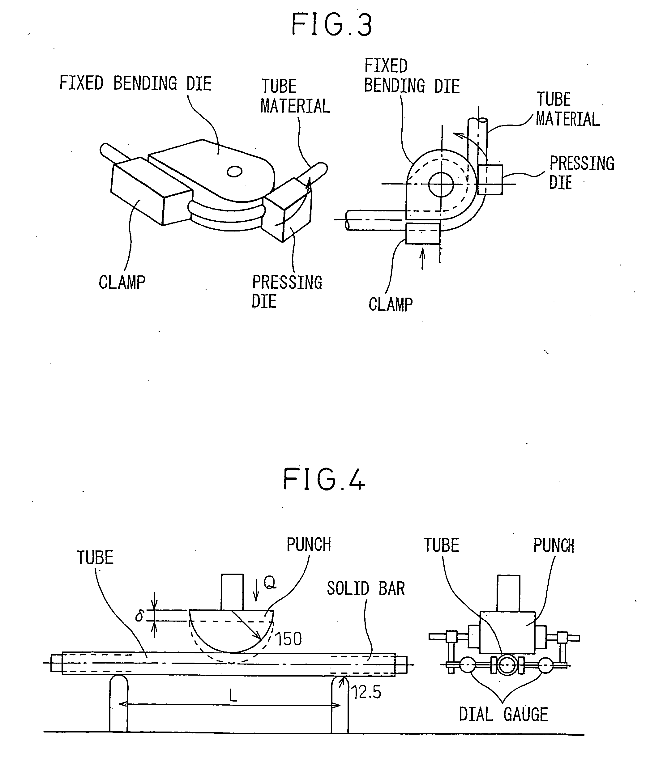
In particular, when the distance between the support points is large, buckling such as crumpling easily occurs at the location pressed by the punch.
However, the drawbacks that the bending shape is limited to a circular arc and that bending by a large bending radius is difficult in terms of equipment are similar to the case of draw bending.

Method used


Image

  • Apparatus and method for ram bending of tube material
  • Apparatus and method for ram bending of tube material
  • Apparatus and method for ram bending of tube material

Examples


example 1

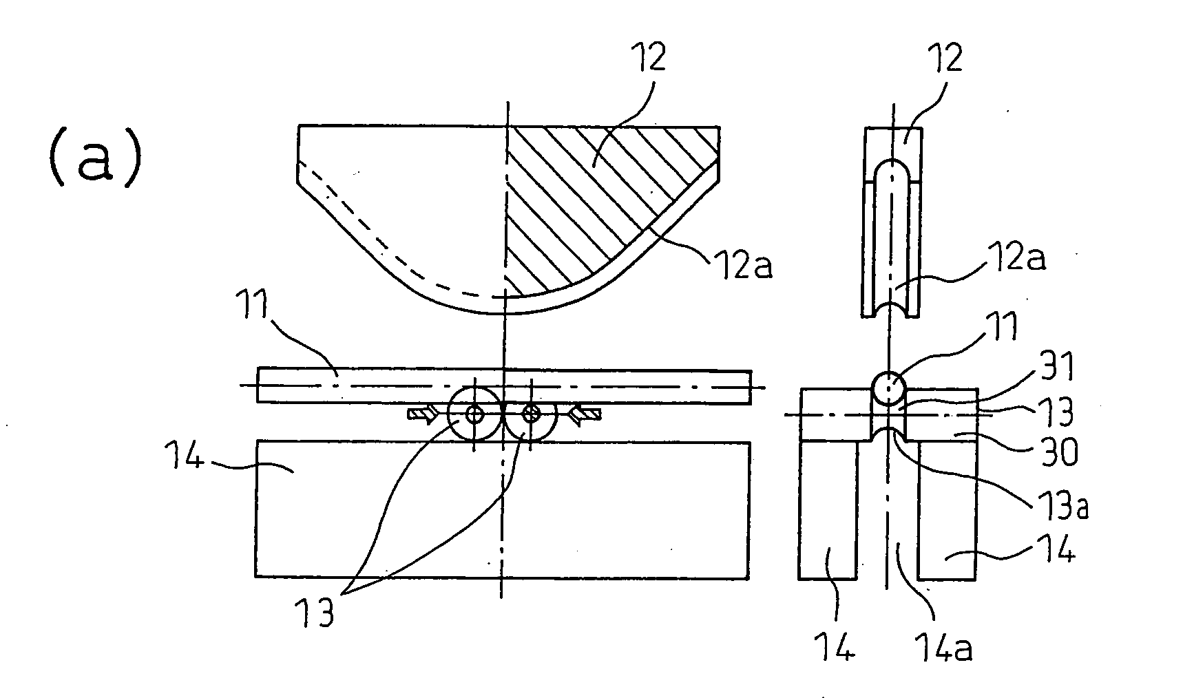
[0088]For the tube material 11 of a circular tube, STKM20A of carbon steel tubes for mechanical structures of an outside diameter of 25.4 mm and a total length of 480 mm was used. The wall thicknesses t were made two types: 2.0 mm and 1.6 mm. At the steel tube, as shown in FIG. 20, the center of the tube material 11 was bent 90° to a circular arc shape of a bending radius of 203.2 mm (8 times the outside diameter). Note that the rolls 13, as shown in FIG. 14, were structured so as not to rotate, but to slide with respect to the frame 14 and with respect to the punch 12. The dimensions, as shown in the same figure, were made R=25.4 mm at the outer side and R=12.7 mm at the inner side (groove bottom). Namely, the bottom surfaces of the end parts 30 of the rolls 13 contacting the frame 14 are designed to be flat surfaces, while the top parts of the roll end parts 30 contacting the punch 12 form semicircular shapes. Further, the grooves 13a of the center parts 31 of the rolls 13 have cr...

example 2

[0089]The same tube material 11 as in Example 1 was used for bending under the same conditions. Only the structure of the rolls 13 was changed. The rolls 13, as shown in FIG. 21, are structured to be able to move over the frame 14 while circular wheels 30 (end parts 30 of the rolls) rotates. The semicircular cross-section hourglass-shaped roll center parts 31 can move with respect to the punch 12 as well while rotating. Note that the shafts 32 connecting with the wheel parts 30 on the frame 14 and hourglass-shaped roll center parts 31 contacting the punch 12 are structured fastened with the roll center parts 31, but can freely rotate with respect to the wheel parts 30. Further, the dimensions of the rolls 13 are an outside diameter of the wheel parts 30 of 48 mm, an outside diameter of the hourglass-shaped roll center parts 31 of 50.8 mm, and a distance between the grooves 13a, 13a of 25.4 mm.

example 3

[0090]A tube material 11, punch 12, frame 14, and rolls 13 the same as with Example 2 were used for bending by pushing in the punch 12 until the same position as with Example 2. However, the rolls 13 were driven to bend the material while forcibly making it rotate. For driving the rolls 13, in this example, as shown in FIG. 22, driving means 40 for driving the rotation of the rolls 13 in a direction making the tube material 11 advance towards the tube ends were used. At the driving means 40, motors 41 and chains 42 which make the shafts 32 of the rolls 13 rotate were arranged to forcibly make the shafts 32 rotate via the chains 42 from the motors 41. Namely, the direction of the rotation was made the direction by which the two rolls 13, 13 head toward the outsides from each other.


PUM

PropertyMeasurementUnit
lengthaaaaaaaaaa
diameteraaaaaaaaaa
thicknessesaaaaaaaaaa

Abstract

The present invention provides a new bending apparatus and bending method of a tube material which makes it possible to achieve all of bending by a large bending radius not requiring large scale equipment or die, bending resistant to wrinkling and buckling at an inner side of the bending, and bending with a high productivity, that is, a ram bending apparatus using a punch 12 and a set of rolls 13, 13 for three-point bending of a tube material wherein the punch 12 has a groove 12a of a width of the width of a circular tube 11 or more and wherein the set of rolls 13, 13 are supported by a frame 14. The rolls 13, 13 can freely move on the frame 14 in directions away from each other in a state contacting the punch 12. The frame 14 has a hollow space 14a enabling free movement of the descending punch 12 and the circular tube 11 bent along with this during the bending of the circular tube 11.

Description

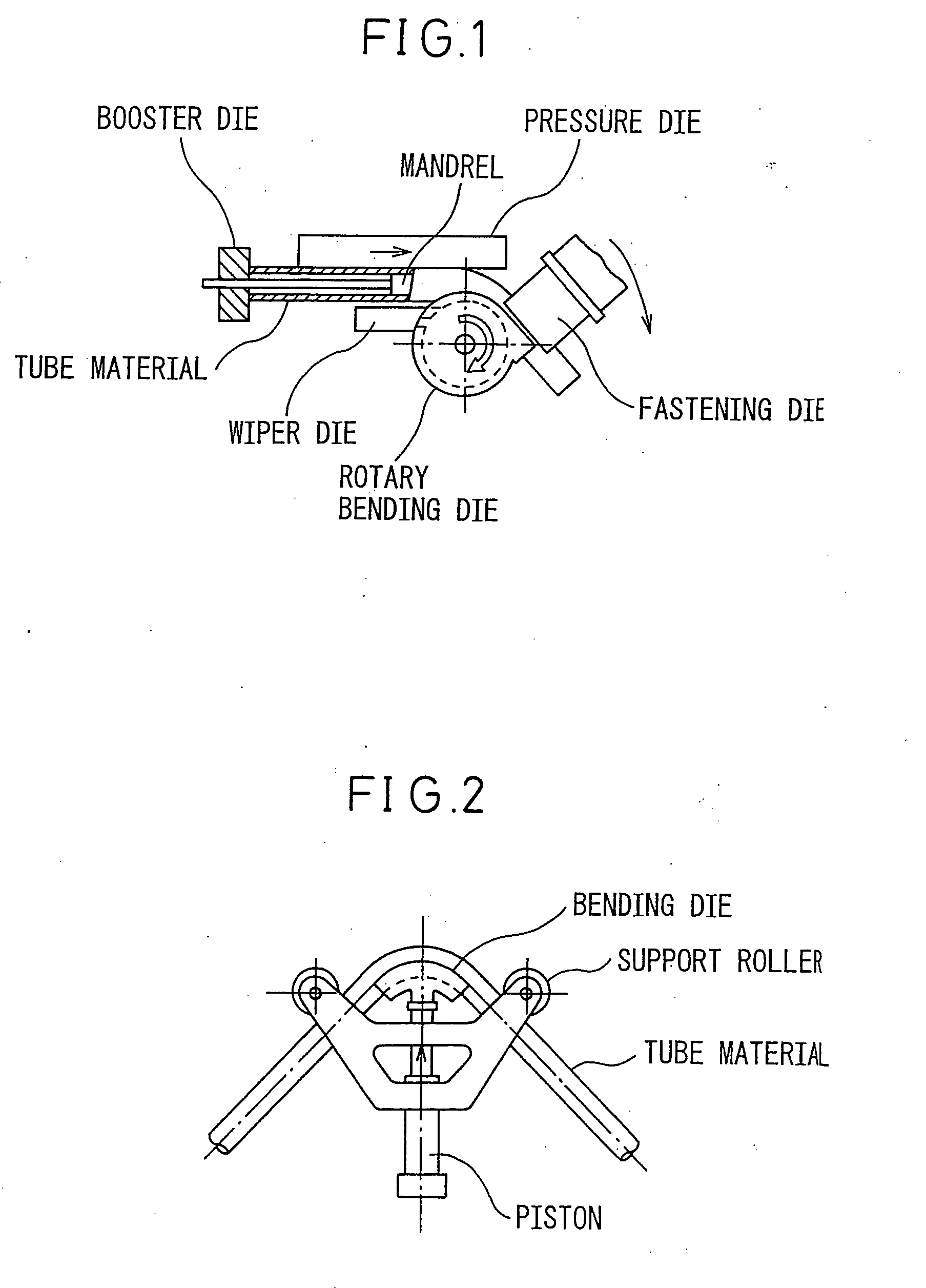
TECHNICAL FIELD[0001]The present invention relates to a bending apparatus and a bending method of a tube material when manufacturing auto parts, building material parts, furniture parts, and the like.BACKGROUND ART[0002]Recently, in the fields of auto parts, building material parts, furniture parts, etc., it has been demanded to lighten the weight as much as possible in a state securing rigidity. As one means for this, making the materials hollow is effective. On the other hand, these parts are increasing being bent in view of the needs for arrangement in small spaces, aesthetic design, assembly of a plurality of parts, etc.[0003]There are very many types of bending methods of tube materials. If giving several examples from “Tube Forming”, page 36 to page 64 (Oct. 30, 1992, Corona Publishing Co., Ltd.), there are draw bending (see FIG. 1), ram bending (see FIG. 2), press bending (see FIG. 3), and the like.[0004]Among these, draw bending is the method most generally being used. The a...

Claims


Application Information

Patent Timeline
Patent Type & Authority Applications(United States)
IPC IPC(8): B21D9/04
CPCB21D7/066B21D7/06B21D7/00B21D9/04
Inventor MIZUMURA, MASAAKIKURIYAMA, YUKIHISA
Owner NIPPON STEEL CORP
Learn More