Compact multiband antenna

Active Publication Date: 2010-01-21
GALTRONICS USA INC
View PDF5 Cites 26 Cited by
  • Summary
  • Abstract
  • Description
  • Claims
  • Application Information

AI Technical Summary

Benefits of technology

[0006]A second element of the antenna comprises a labyrinthine coupling element which is mounted on the bounding surface, in proximity to the monopole. The coupling element may be formed of one conducting section. Alternatively, the coupling element comprises multiple conducting sections galvanically connected together. The coupling element partially envelopes the monopole, is connected to a ground, and acts to couple electric and magnetic fields between the monopole and the ground. The partial envelopment by the coupling element is typically three-dimensional, and allows the antenna to have a small overall volume.
[0007]The coupling results in enhanced bandwidth for the antenna, by using radiation properti

Problems solved by technology

Costs have to be minimized, and typically the devic

Method used


Image

  • Compact multiband antenna
  • Compact multiband antenna
  • Compact multiband antenna

Examples


Embodiment Construction

Overview

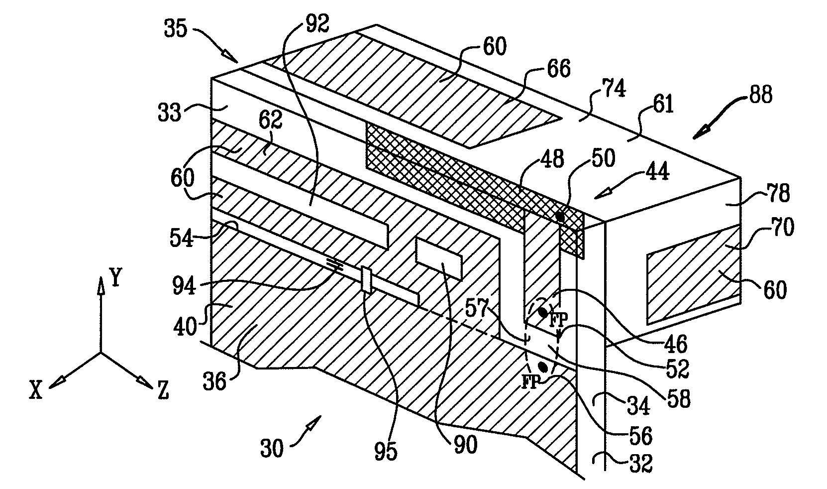
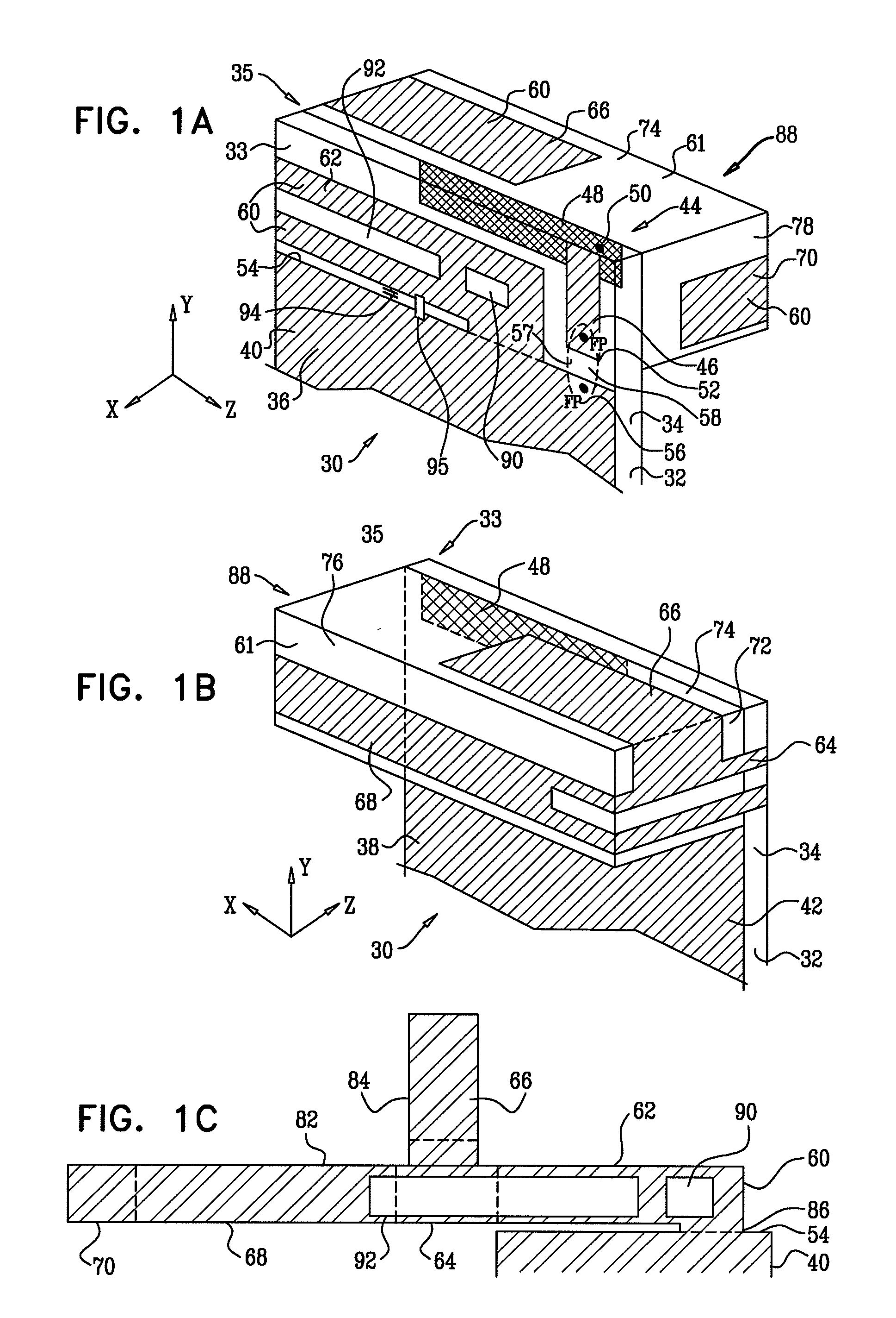
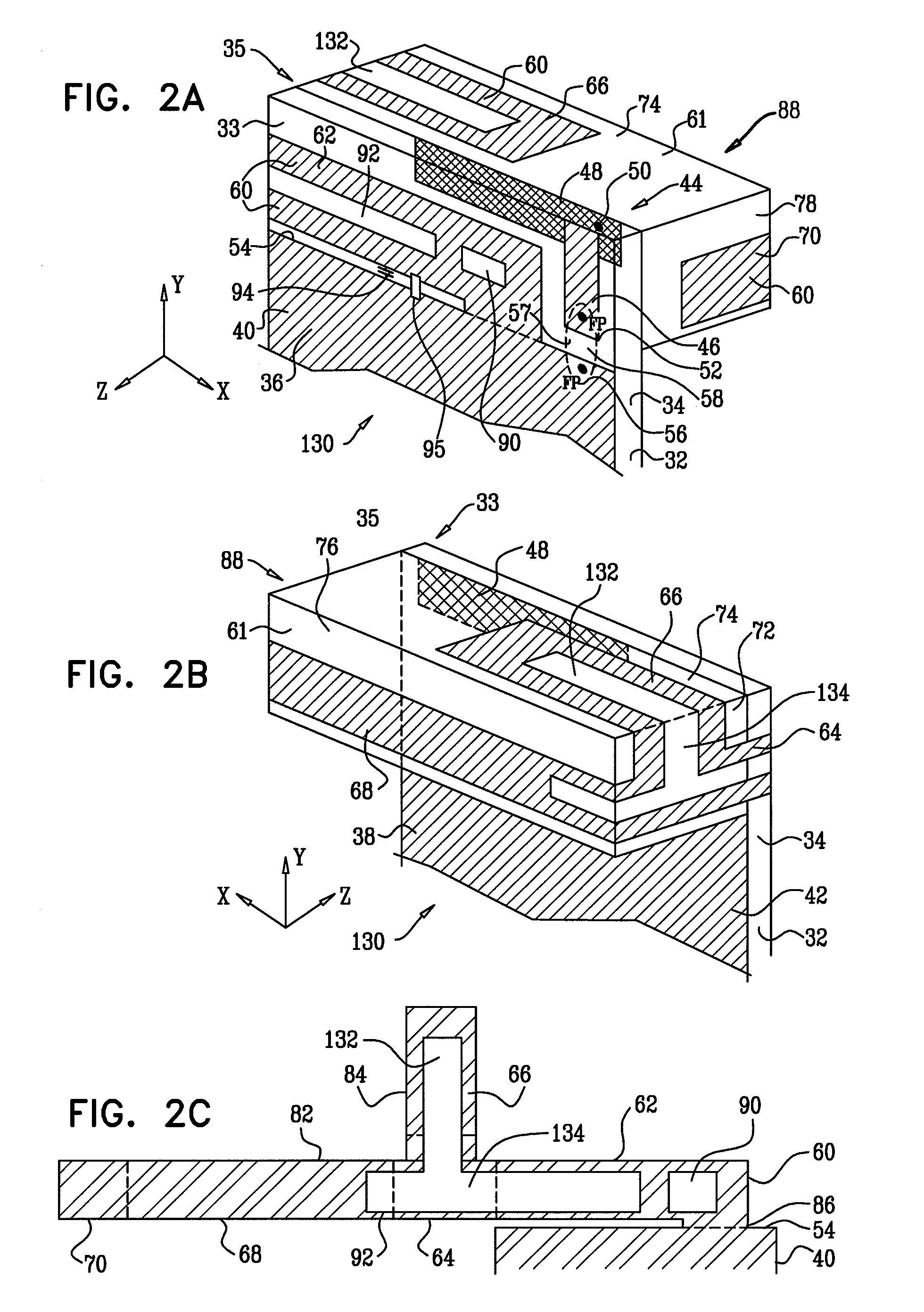
[0071]Antennas described herein comprise a high frequency resonator, and a coupling element, placed in proximity to, but insulated from, the resonator. The coupling element couples electric and magnetic fields between the resonator and a ground. The coupling element may be conveniently mounted or formed on the surface of a dielectric carrier, and at least a portion of the high frequency resonator may also be on the surface.

[0072]The antennas have a feed region consisting of an end of the resonator and a section of the ground. If the feed region is fed by high and low frequencies, the coupling element couples and transfers the low frequencies to the ground, from where they radiate. If the coupling is relatively high for higher frequencies, the high frequencies also transfer and radiate from the ground, and the bandwidth of the antennas is broad. The antennas may thus be configured as good wide bandwidth radiators for low and high frequencies.

[0073]In one embodiment the high f...


PUM

PropertyMeasurementUnit
Frequencyaaaaaaaaaa
Frequencyaaaaaaaaaa
Frequencyaaaaaaaaaa

Abstract

An antenna, including a dielectric carrier having a bounding surface, and a conductive monopole resonant at a first frequency, the monopole having at least one conducting section mounted on the bounding surface. The antenna further includes a labyrinthine conductive coupling element mounted on the bounding surface so as to encompass the dielectric carrier. The coupling element is located with respect to the conductive monopole so as to transfer from the conductive monopole a second frequency lower than the first frequency.

Description

CROSS-REFERENCE TO RELATED APPLICATION[0001]This application claims the benefit of U.S. Provisional Patent Application 61 / 134,990, filed Jul. 15, 2008, which is incorporated herein by reference.FIELD OF THE INVENTION[0002]The present invention relates generally to antennas, and specifically to compact antennas that may be used in multiple bands.BACKGROUND OF THE INVENTION[0003]There are a number of conflicting demands that have to be balanced in order to efficiently produce communication devices, such as cellular telephones or personal digital assistants (PDAs). Costs have to be minimized, and typically the devices themselves are becoming smaller yet more complex. In addition, devices that relatively recently were only required to operate efficiently on one or two wavelength bands may now be required to operate, with substantially the same efficiency, over five or more bands. A critical component in implementing this efficient operation is a correctly designed antenna that meets all...

Claims


Application Information

Patent Timeline
IPC IPC(8): H01Q7/00H01P11/00H01Q1/38H01Q1/48H01Q1/50H01Q5/378
CPCH01Q1/243H01Q1/38H01Q5/378Y10T29/49016H01Q9/42
Inventor KAPULIANSKY, EPHRAIMMARTISKAINEN, MATTIBEREZIN, ANATOLYKRUPA, STEVE
Owner GALTRONICS USA INC
Why Eureka
Try Eureka