
Stereo viewer

Inactive Publication Date: 2010-01-21
VIVID MEDICAL
View PDF7 Cites 72 Cited by
  • Summary
  • Abstract
  • Description
  • Claims
  • Application Information

AI Technical Summary

Benefits of technology

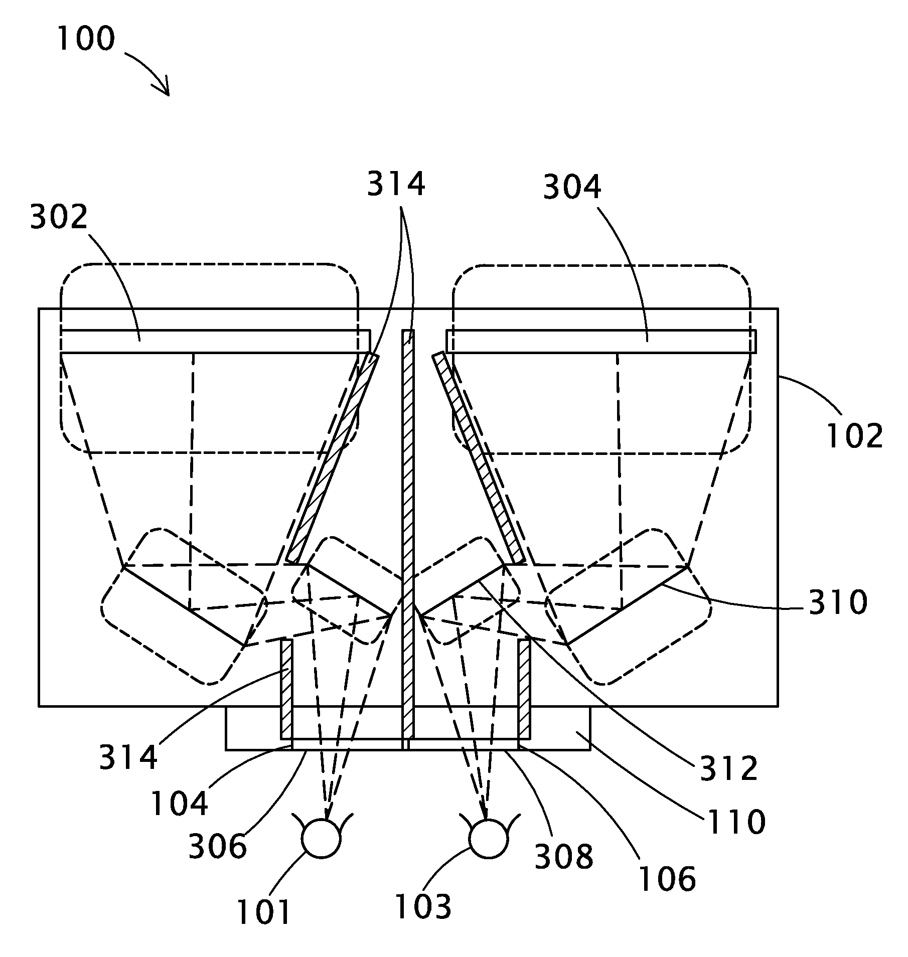
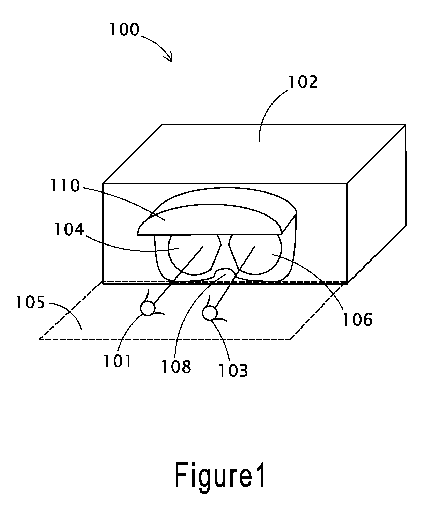
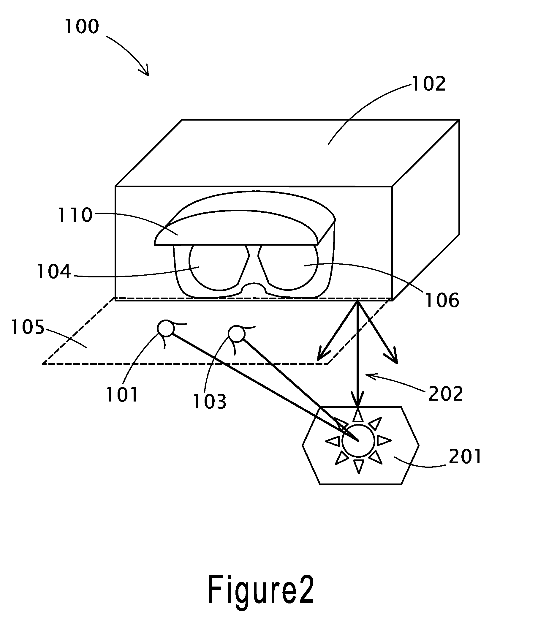
[0012]These and other limitations may be overcome by embodiments of the disclosure which relate to small, high resolution 2-dimensional (2D) or 3D stereo viewers that are fully maneuverable in the surgical environment and can be positioned above the patient without any physical attachment to the user's head. The present 3D stereo viewer may be conveniently adjusted to a fixed location in space for optional viewing of the 3D information, where the surgeon may move their head and direct their line of sight easily to the patient and the 3D viewer at any time.
[0013]The 3D viewer of the present disclosure may have a cut out portion or a free space opening, at the front bottom portion of the 3D viewer. The 3D stereo viewer may be set at a comfortable distance from the user's head, where the user can easily gain a lower line of site to the area of observation simply by looking down. Also, by having a relatively larger distance from the user's eyes and the physical space that the user can comfortably gain 3D viewing, the surgeon may be free to lower or tilt his or her head for optimum viewing of the actual surgical site. The user may also be free to move their head farther away from the 3D viewer and to the sides to perform other surgical tasks.

Problems solved by technology

This both reduces the risk of infection and reduces the patient's hospital stay.
However, current stereo viewing in surgical environment is limited to large stereo consoles using dual display systems, or head mounted displays that must be worn in a fixed fashion on the head.
Large 3D stereo viewers limit the use of the stereo viewer to a position near or at a remote surgical site, where the surgery is performed by tele-robotic arms.
The head-mounted solution, such as in eye-glass or goggle type 3D stereo displays fixed on the surgeon's head, are disorienting to the surgeon.
The head mounted display solutions also limit the visual field of the surgical staff.
This limits how far away the goggle or head mount displays can be with respect to a user's eye.
Partial views of the actual surgical site, either by making the displays partially transparent, or by limiting the area of the eye the display covers, are not acceptable.
Head mount displays are also cumbersome to remove and / or re-position for optimal viewing.

Method used


Image

  • Stereo viewer
  • Stereo viewer
  • Stereo viewer

Examples


Embodiment Construction

[0030]Embodiments of the current disclosure are directed to general individual display units that can enable 3D stereo viewing of medical stereoscopic or binocular images. 3D stereo images can be captured using stereo endoscopes in a variety of forms, such as rigid, semi-rigid, and flexible, endoscopes with any fields of view (FOV), as well as angled endoscopes with various directions of view.

[0031]Stereo images captured during stereo digital microscopy or stereo micro surgery, representing 3D tissue structure or organ inside the body or on the skin, can be viewed in real time using the 3D stereo viewer. Past 3D imaging information obtained in similar manner or reconstructed from various other medical imaging mechanisms such as MRI, Ultrasound, CT scan, etc., may also be played on the stereo viewer at the same time as the real time video images.

[0032]The stereo images whether taken in the visual spectrum of light or in Infrared or UV imaging, or as a result of bio fluorescence spect...


PUM


Abstract

Various embodiments of opto-electronic display modules for viewing real time, stored or computer generated images and video information in 3D or 2D are presented. The various 2D or 3D viewer embodiments of the present disclosure allow independent use of the imaging information in a way that is convenient to the user without affecting the other tasks that the user needs to perform. Multiple viewers of the present embodiment can be used concurrently by multiple users, where each viewer is fully maneuverable and controllable for and by each specific user. Additionally, the viewer of the present disclosure may communicate to various input devices as well as send user commands to such devices in an electrical, optical, or wireless transmission format.

Description

CROSS-REFERENCE TO RELATED APPLICATIONS[0001]This application claims the benefit of and priority to U.S. Provisional Patent Application No. 61 / 082,432 filed Jul. 21, 2008, and entitled “Individual Stereo Viewer,” the disclosure of which is incorporated herein by reference in its entirety.BACKGROUND[0002]1. The Technical Field[0003]The present disclosure relates generally to apparatus for electronic stereo viewing of medical and pathological images. Binocular electronic stereo images can be captured using stereo endoscopes in variety of endoscopic surgical applications using 3-dimensional (3D) medical imaging equipment, as well as in pathology examination of specimens in 3D under stereo microscope equipment with dual electronic image capture devices. The present disclosure describes an apparatus for viewing of such stereo images.[0004]2. Related Technology[0005]Endoscopes of a variety of forms are used both in both diagnostic and surgical procedures. Currently, minimally invasive sur...

Claims


Application Information

Patent Timeline
IPC IPC(8): H04N13/04G02B27/22G06F3/041G10L15/00
CPCG02B7/001H04N13/044G06F3/011G02B27/2235G02B30/35H04N13/344
Inventor FARR, MINA
Owner VIVID MEDICAL
Learn More