Ceramic matrix composite wall with post laminate stitching

a composite wall and ceramic matrix technology, applied in the field of ceramic matrix composite walls, can solve the problems of high cost, high cost, and inability to achieve oxide-based cmcs without considerable investment, and achieve the effects of reducing the cost of brittle fiber preform, high cost, and high cos

Inactive Publication Date: 2010-01-21
SIEMENS ENERGY INC
View PDF20 Cites 34 Cited by
  • Summary
  • Abstract
  • Description
  • Claims
  • Application Information

AI Technical Summary

Problems solved by technology

However, interlaminar stresses work to damage the interlayer bonds and separate the layers.
However, this technique is not feasible for oxide-based CMCs without considerable investment, because infiltrating a particulate loaded ceramic slurry into a thick, tightly packed, brittle fiber preform is extremely difficult.
It can result in incomplete and heterogeneous matrix infiltration, even when using state-of-the-art processing, and even for relatively thin 3D preforms such as 3-4 mm.
The problem is worse with more realistic component wall thicknesses such as 5 mm or more.
However, these large particle sizes are especially difficult to infiltrate into a thick, densely packed fibrous preform, because the preform acts as a filter.
Not conducive to localized optimization of reinforcement geometry
High development costs for complex shapes, due to custom loom setups, etc.
3D preforms often cannot be compacted for maximum fiber volume without losing the through-thickness reinforcement benefit
Long development time & expense precludes iterative design approaches
Expertise resides in a limited number of specialty shops, none of which offer all available options.

Method used


Image

  • Ceramic matrix composite wall with post laminate stitching
  • Ceramic matrix composite wall with post laminate stitching
  • Ceramic matrix composite wall with post laminate stitching

Examples


Embodiment Construction

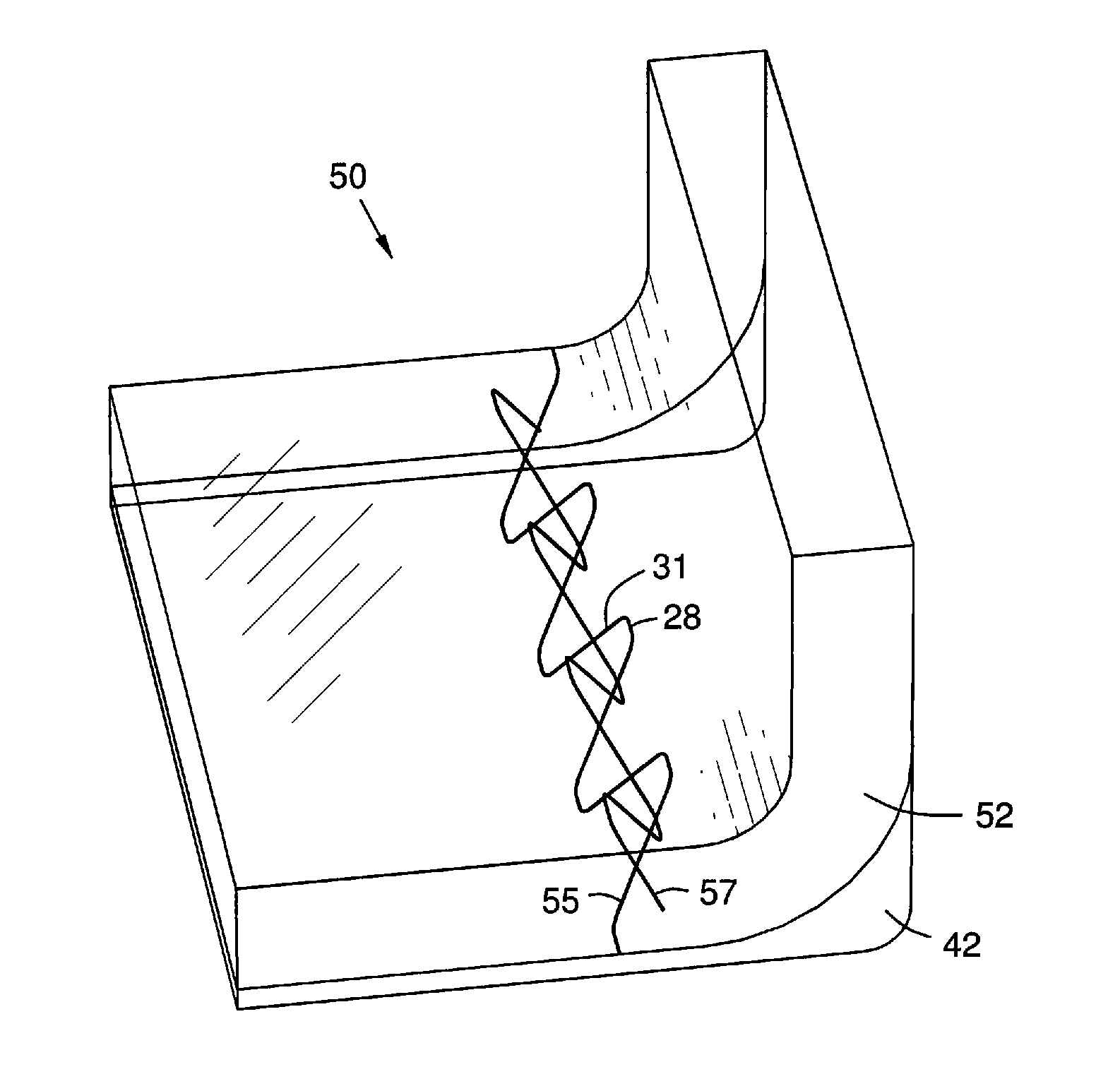
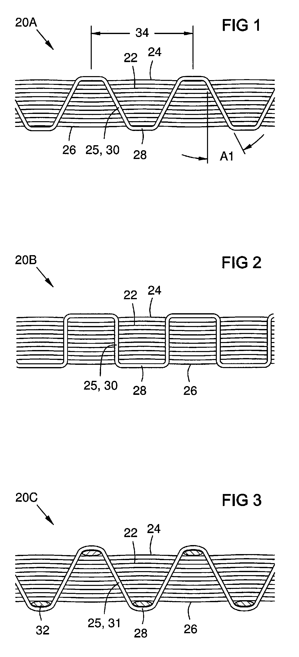
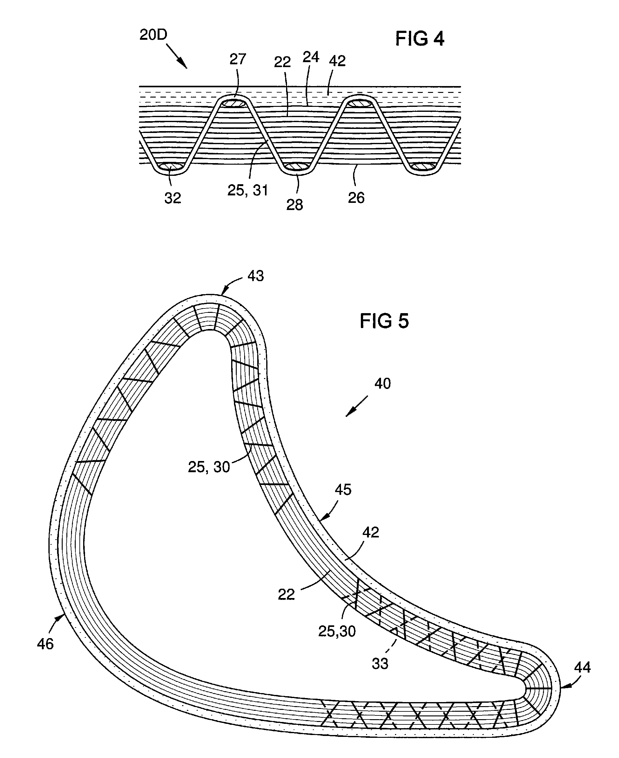
[0022]The invention provides selective through-thickness reinforcement applied to a CMC laminated wall after the laminae are stacked and partially or fully cured. Holes may be formed in the wall after at least partial curing, and a ceramic fiber thread is passed through the holes to form a row of stitches. The thread is infiltrated with a wet ceramic matrix before or after stitching, and then heated / cured after stitching. The ceramic fibers and matrix of the thread shrink during firing, thus creating a tensile preload in the stitches. Selection of a firing temperature for the CMC wall, and selection of the type of thread fiber determines the amount of tensile preload created.

[0023]For example, bisque firing of the CMC wall can partially shrink the wall in order to leave a remaining shrinkage approximately equal to the full shrinkage of a thermal barrier coating (TBC) during a final curing. The present stitching may be done after the bisque firing and before applying the TBC. If wet ...


PUM

PropertyMeasurementUnit
thicknessesaaaaaaaaaa
sizeaaaaaaaaaa
diameteraaaaaaaaaa

Abstract

A stitching geometry and method for selective interlaminar reinforcement of a CMC wall (20A). The CMC wall is formed of ceramic fiber layers (22) individually infused with a ceramic matrix, stacked, and at least partially cured. A row of holes is formed in the wall, and a ceramic fiber thread (25) is infused with a wet ceramic matrix and passed through the holes to form stitches (28, 30, 31). The stitches are then cured, causing them to shrink more than any remaining wall shrinkage, thus tensioning the stitches and compressing the wall laminae together. The stitches may have through-wall portions (30, 31) that are angled differently in different wall areas as a function of interlaminar shear over interlaminar tension, optimizing wall reinforcement locally depending on magnitude and direction of shear. Alternate rows of stitches (54, 56) may have offsets in a stitch direction (34) and/or different through-wall angles (A1, A2).

Description

FIELD OF THE INVENTION[0001]This invention relates to ceramic matrix composite (CMC) walls formed of laminated sheets of ceramic fibers, and particularly to interlaminar reinforcement methods and mechanisms for such walls.BACKGROUND OF THE INVENTION[0002]Ceramic matrix composites (CMC) are used for components in high-temperature areas of gas turbines. CMC walls may be formed by laminating multiple layers of ceramic fabric or fibers in a ceramic matrix. However, interlaminar stresses work to damage the interlayer bonds and separate the layers. Alternately, three-dimensionally woven CMC walls offer improved through-thickness properties over 2D laminated walls. 3D walls are reinforced at the preform stage, during which a ceramic fiber structure is woven to nearly final shape by weaving, braiding, or knitting. However, this technique is not feasible for oxide-based CMCs without considerable investment, because infiltrating a particulate loaded ceramic slurry into a thick, tightly packed...

Claims


Application Information

Patent Timeline
Patent Type & Authority Applications(United States)
IPC IPC(8): B32B5/26B32B3/10
CPCB28B1/002B28B23/0006B32B18/00C04B35/6269C04B35/80Y10T428/24322C04B2237/38C04B2237/62F01D5/282F05D2300/702C04B2235/5224C04B2235/616C04B2235/6028C04B35/01C04B2237/34
Inventor MORRISON, JAY A.LANE, JAY E.
Owner SIEMENS ENERGY INC
Why Eureka
Try Eureka