Legged robot

a robot and leg technology, applied in the field of leg robots, can solve the problems of inability to perfectly simulate the motion of the leg robot, inability to compensate by successive feedback control, and errors between the motions realized on the computer in accordance,

Inactive Publication Date: 2010-01-21
TOYOTA JIDOSHA KK
View PDF4 Cites 42 Cited by
  • Summary
  • Abstract
  • Description
  • Claims
  • Application Information

AI Technical Summary

Benefits of technology

[0010]As in the case of “running”, during the transition from the aerial phase to the ground-contact phase, the state of the legged robot discontinuously shifts from the airborne state (state in which the legs are not in contact with the ground) to the state in which the leg comes in contact with the ground. This discontinuous transition timing is, in other words, the landing timing described above. Upon the landing timing, if the simulation errors become discontinuously obvious, the compensation by the successive feedback control as in the case of walking may be difficult; and the motion of the robot may easily become instable. Especially for the legged robot having two legs, instability in the motion may lead to a tumble. Therefore, in order to achieve a stable running, it is desirable for the legged robot to eliminate the influence of the simulation errors on the landing timing as much as possible.
[0012]The present invention focuses on a fact that the “running” and the “hopping” are continuation of the periodic jump motion. Since the jump motion is periodical, it is expected that a time difference between the target aerial phase period (target value of the aerial phase period) and the actual aerial phase period measured when the robot has actually jumped in the pervious jump cycle is approximately the same value in the current jump cycle. Therefore, if the vertical velocity of the center of gravity at the takeoff timing in the current jump cycle is determined based on the time difference in the previous jump cycle, it is possible to eliminate the time difference in the current jump cycle. In other words, it is possible to compensate the simulation error on the landing timing. Although it is desirable to determine the vertical velocity of the center of gravity at the takeoff timing in the current jump cycle based on the time difference in the previous jump cycle, a similar effect is provided if the vertical velocity of the center of gravity at the takeoff timing in the current jump cycle is determined based on the time difference in a specific past jump cycle. The vertical velocity may be determined based on time differences of a plurality of past jump cycles. In other words, such an effect is provided by driving joints of the robot based on the time difference between the target aerial phase period and the actual aerial phase period.
[0014]According to the above legged robot, the joints are driven based on the time difference between the target aerial phase period and the actual aerial phase period. As a result, as described above, it is possible to coincide the landing timing when the robot actually jumps with the landing timing obtained by the simulation in advance.
[0018]A contact sensor, for example, may easily and precisely detect whether the leg is in contact with the ground or not. Therefore, the actual aerial phase period can be easily and precisely detected by the contact sensor. On the other hand, it is difficult to precisely measure the velocity of the center of gravity. According to one aspect of the present invention, the target vertical velocity of the center of gravity of the legged robot at the takeoff timing in the current jump cycle is determined based on the time difference in the previous jump cycle (past jump cycle). As a result, the target vertical velocity of the center of gravity of the legged robot can be determined without measuring the actual velocity of the center of gravity at the takeoff timing.
[0020]The above configuration enables a smooth shift of vertical velocity of the center of gravity in the ground-contact phase (i.e. period from the landing to the next takeoff). The motion of the robot from the landing to the takeoff may be smoothed.
[0023]According to the present invention, it is possible to provide a legged robot which runs while adjusting the actual landing timing so as to coincide with the landing timing planned in advance by the computer simulation.

Problems solved by technology

It is not possible to perfectly simulate the motion of the robot.
Therefore, there may be errors between the motion realized on a computer in accordance with the generated motion data and the actual motion.
Upon the landing timing, if the simulation errors become discontinuously obvious, the compensation by the successive feedback control as in the case of walking may be difficult; and the motion of the robot may easily become instable.
Especially for the legged robot having two legs, instability in the motion may lead to a tumble.
One of the major simulation errors which discontinuously appear upon the landing timing is a deviation between the landing timing obtained by the simulation (namely, the landing timing based on the gait data) and the landing timing in the actual running of the robot.

Method used


Image

  • Legged robot
  • Legged robot
  • Legged robot

Examples


Embodiment Construction

[0027]A description will now be given of a preferable legged robot with reference to drawings.

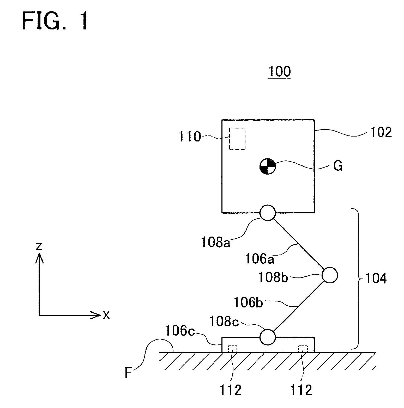
[0028]FIG. 1 shows a schematic side view of a legged robot 100. The legged robot 100 is a robot in which one leg 104 is connected to a trunk link 102. Although the robot may have any number of legs, the present embodiment exemplifies a legged robot having one leg 104 for the sake of easy understanding of the motion of the robot.

[0029]The leg 104 of the robot 100 includes three links 106a, 106b, 106c, and three joints 108a, 108b, 108c. The three links 106a, 106b, 106c are hereinafter referred to as “links 106” in general. Similarly, the three joints 108a, 108b, 108c are collectively referred to as “joints 108” hereinafter.

[0030]The joint 108a rotatably connects the trunk link 102 and the link 106a with each other. The joint 108b rotatably connects the link 106a and the link 106b with each other. The joint 108c rotatably connects the link 106b and the link 106c with each other. The link 106c ...


PUM


Abstract

A legged robot that runs while repeating a jump cycle including a ground-contact phase from a landing to a takeoff and an aerial phase from a takeoff to a landing is provided. The legged robot adjusts the landing timing after a jump in accordance with a planned timing, thereby attaining a smooth landing. A measuring unit of the legged robot measures an actual aerial phase period in a k-th jump cycle. A subtractor calculates a time difference between a target aerial phase period and the actual aerial phase period in the k-th jump cycle. A target velocity determining unit calculates a target vertical velocity of a center of gravity on a takeoff timing in a (k+1)-th jump cycle so as to eliminate the time difference. Motors in respective joints are controlled so as to realize the calculated target vertical velocity in the (k+1)-th jump cycle. As a result, the time difference generated in the k-th jump cycle in the (k+1)-th jump cycle can be compensated, thereby adjusting the landing timing with the planned landing timing, resulting in the jump motion with smooth landing.

Description

CROSS-REFERENCE TO RELATED APPLICATION[0001]This application claims priority to Japanese Patent Application No. 2006-242169, filed on Sep. 6, 2006, the contents of which are hereby incorporated by reference into the present application.BACKGROUND OF THE INVENTION[0002]1. Field of the Invention[0003]The present invention relates to a legged robot capable of running. It should be noted that a legged robot may be simply referred to as “robot” hereinafter.[0004]2. Description of the Prior Art[0005]Legged robots which can move by driving the joints disposed in the legs are being developed. The number of the legs may vary in robots. A biped robot moves like a human, and a quadruped robot moves like an animal. A monoped robot moves while hopping.[0006]Humans and animals present a behavior of “running” rather than “walking” for a fast travel. It is also preferable for legged robots being able to perform the behavior of “running” for a fast travel. “Walking” is a movement in which at least o...

Claims


Application Information

Patent Timeline
Patent Type & Authority Applications(United States)
IPC IPC(8): B25J5/00B25J13/00
CPCB62D57/032
Inventor SUGA, KEISUKEHONDA, DAISAKUMIYAGAWA, TORUTAJIMA, RYOSUKE
Owner TOYOTA JIDOSHA KK
Why Eureka
Try Eureka